
ABB XAC26284 Manuale utente

Turbo Systems Switzerland Ltd
Operation Manual / A165-L34
XAC26284
Document identification
Document number HZTL4034
Revision T
Language English
Original Operation Manual
Product identification
Serial number XAC26284
Customer part number AV65MZ01411
Delivery date (yyyy-mm-dd) 2022-04-01
Weight 2300 kg
Operating limits according to rating plate
Speed limit in test rig operation only nMmax 382 1/s
Speed limit during operation nBmax 361 1/s
Gas inlet temperature limit in test rig operation only tMmax 550 °C
Gas inlet temperature limit during operation tBmax 520 °C


Operation Manual / A100-L
Table of contents
© Copyright 2021 ABB. All rights reserved. HZTL4034_EN Rev.T December 2021
Operation Manual / A100-L
1 Introduction............................................................................................................ 4
1.1 Essential information.................................................................................................... 5
1.2 Registered trademarks................................................................................................. 5
1.3 Layout and function of the turbocharger ................................................................ 6
1.4 Locations of the rating plates.................................................................................... 8
2 Safety ...................................................................................................................... 9
2.1 Introduction ................................................................................................................... 9
2.2 CE conformity................................................................................................................ 9
2.3 Definition of mandatory signs .................................................................................. 10
2.4 Definition of safety instructions .............................................................................. 10
2.5 Intended use ................................................................................................................. 11
2.6 Deflagration on gas engines ..................................................................................... 12
2.7 Warning plates on the turbocharger........................................................................ 13
2.8 Turbocharger rating plate.......................................................................................... 13
2.9 Periodic check of the pressure vessels.................................................................... 15
2.10 Lifting of loads ............................................................................................................. 16
2.11 Prerequisites for operation and maintenance....................................................... 17
2.12 Hazards during operation and maintenance ......................................................... 18
2.13 Safe operation.............................................................................................................. 19
2.14 Safe maintenance ....................................................................................................... 20
3 Removal and installation .................................................................................... 25
3.1 Turbocharger weight ................................................................................................. 25
3.2 Removing the turbocharger...................................................................................... 25
3.3 Installing the turbocharger ....................................................................................... 27
4 Commissioning .................................................................................................... 30
4.1 Oil supply ...................................................................................................................... 30
4.2 Inspection procedures............................................................................................... 30
4.3 Commissioning after taking out of operation....................................................... 32
5 Monitoring during operation.............................................................................. 33
5.1 Oil pressure, oil temperature.................................................................................... 33
5.2 Admissible air inlet temperature ............................................................................. 36
5.3 Turbocharger speed ................................................................................................... 36
5.4 Low pressure measurement at the filter silencer ................................................ 39
6 Operation and service ......................................................................................... 40
6.1 Noise emission ............................................................................................................ 40
6.2 Service work.................................................................................................................. 41
6.3 Expected replacement intervals .............................................................................. 45
6.4 Flexible turbocharger cut-out .................................................................................. 46

Operation Manual / A100-L
Table of contents
© Copyright 2021 ABB. All rights reserved. HZTL4034_EN Rev.T December 2021
6.5 Stopping the engine................................................................................................... 47
7 Periodic maintenance.......................................................................................... 48
7.1 Foreword to maintenance......................................................................................... 48
7.2 Cleaning the filter silencer ........................................................................................ 49
7.3 Changing the filter strip on the filter silencer casing........................................... 51
7.4 Cleaning the compressor during operation .......................................................... 53
7.5 Cleaning the turbine during operation.................................................................... 57
7.6 Draining the gas outlet casing .................................................................................. 61
8 Troubleshooting................................................................................................... 62
8.1 Malfunctions when starting...................................................................................... 62
8.2 Malfunctions during operation ................................................................................ 63
8.3 Surging of the turbocharger..................................................................................... 65
8.4 Malfunctions when stopping.................................................................................... 66
8.5 Speed measurement system.................................................................................... 67
9 Disassembly and assembly................................................................................. 68
9.1 Introduction ................................................................................................................. 68
9.2 Material required......................................................................................................... 69
9.3 Weights of assemblies............................................................................................... 70
9.4 Disassembly and assembly of the filter silencer casing ...................................... 71
9.5 Dismantling the filter silencer .................................................................................. 76
9.6 Dismantling the filter silencer with noise package ............................................. 78
9.7 Dismantling wall insert and diffuser....................................................................... 79
9.8 Axial clearance A prior to disassembly ................................................................... 83
9.9 Dismantling the insulation (≤ A175-L)..................................................................... 84
9.10 Dismantling the gas inlet casing (≤ A175-L) .......................................................... 85
9.11 Dismantling the nozzle ring (≤ A175-L) ................................................................... 86
9.12 Dismantling the gas inlet casing (≥ A180-L).......................................................... 87
9.13 Dismantling the nozzle ring (≥ A180-L)................................................................... 88
9.14 Fitting the nozzle ring (≤ A175-L) ............................................................................. 90
9.15 Fitting the gas inlet casing (≤ A175-L) ..................................................................... 91
9.16 Fitting the insulation (≤ A175-L)............................................................................... 92
9.17 Fitting the nozzle ring (≥ A180-L) ............................................................................ 93
9.18 Fitting the gas inlet casing (≥ A180-L).................................................................... 95
9.19 Axial clearance A after assembly.............................................................................. 96
9.20 Fitting the diffuser ..................................................................................................... 97
9.21 Fitting wall insert ........................................................................................................ 98
9.22 Fitting the filter silencer.......................................................................................... 100
9.23 Fitting the filter silencer with noise package ..................................................... 103
9.24 Table of tightening torques.................................................................................... 105
10 Taking a turbocharger out of operation......................................................... 107
10.1 Possible emergency repairs.................................................................................... 107
10.2 Taking defective turbochargers out of operation ............................................. 108
11 Mothballing the turbocharger........................................................................... 113

Operation Manual / A100-L
Table of contents
© Copyright 2021 ABB. All rights reserved. HZTL4034_EN Rev.T December 2021
11.1 Taking the engine out of operation for up to 12months .................................. 113
11.2 Taking the engine out of operation for more than 12months ......................... 114
12 Material and Disposal........................................................................................ 115
12.1 REACH and RoHS Compliance Declaration For Products .................................. 115
12.2 Disposing of turbocharger components .............................................................. 116
13 Spare parts .......................................................................................................... 117
13.1 Ordering spare parts................................................................................................. 117
13.2 Spare Part - Illustrations........................................................................................... 119
14 Tools .................................................................................................................... 137
Figures................................................................................................................. 138
Tables .................................................................................................................. 140

Operation Manual / A100-L
1 Introduction /
© Copyright 2021 ABB. All rights reserved. HZTL4034_EN Rev.T December 2021
1 Introduction
Page 4 / 141

Operation Manual / A100-L
1 Introduction / 1.1 Essential information
© Copyright 2021 ABB. All rights reserved. HZTL4034_EN Rev.T December 2021
1.1 Essential information
Design variants
This document is valid for different design variants of turbochargers. There may be sections
and descriptions of components that are not relevant for a specific turbocharger variant.
Please contact an ABB Turbocharging Service Station if you have any questions regarding a
design variant (see Contact information at www.abb.com/turbocharging).
Accuracy of illustrations
The illustrations in this document are general in nature and intended for ease of understand-
ing. Differences in detail are therefore possible.
1.2 Registered trademarks
The trademarks of outside companies are used in this document. These are marked with the
® symbol.
Page 5 / 141
Operation Manual / A100-L
1 Introduction / 1.3 Layout and function of the turbocharger
© Copyright 2021 ABB. All rights reserved. HZTL4034_EN Rev.T December 2021
1.3 Layout and function of the turbocharger
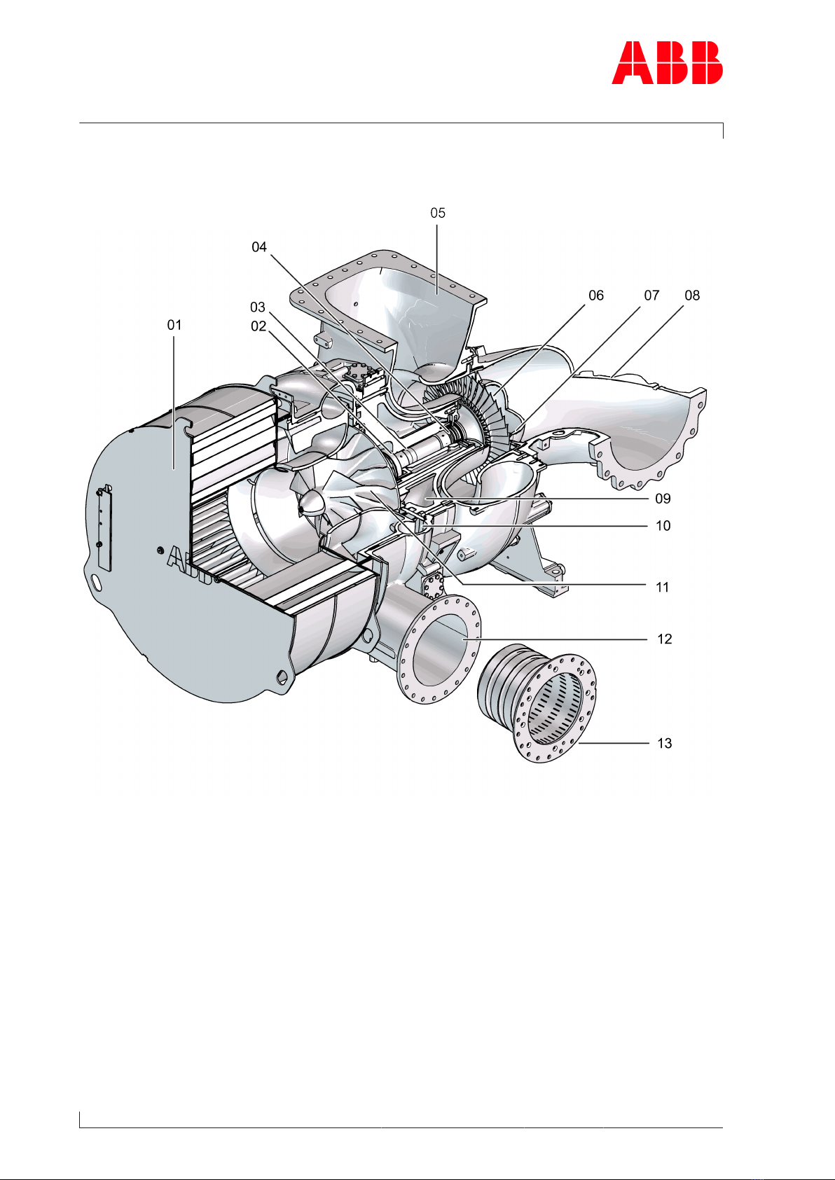
Fig.1: Layout and function of the turbocharger
01 Filter silencer 08 Gas inlet casing
02 Thrust bearing 09 Bearing casing
03 Radial plain bearing 10 Diffuser
04 Radial plain bearing 11 Compressor wheel
05 Gas outlet casing 12 Compressor casing
06 Turbine wheel 13 Air-outlet silencer (option)
07 Nozzle ring
Page 6 / 141

Operation Manual / A100-L
1 Introduction / 1.3 Layout and function of the turbocharger
© Copyright 2021 ABB. All rights reserved. HZTL4034_EN Rev.T December 2021
Mode of operation
The turbocharger is a turbomachine and consists of the following main components:
¡Turbine
¡Compressor
These components are installed on a common shaft and form the rotor.
The exhaust gases of the internal combustion engine flow through the gas inlet casing (08)
and the nozzle ring (07) onto the turbine wheel (06). The turbine wheel uses the energy con-
tained in the exhaust gas to drive the rotor and, hence, the compressor wheel(11).
The exhaust gases then reach the atmosphere through the exhaust gas pipe connected to
the gas outlet casing(05).
The compressor wheel (11) sucks in fresh air and presses the compressed air into the cylin-
ders.
The air passes through the filter silencer(01) to the compressor wheel(11). The air then
flows through the diffuser(10) and exits the turbocharger through the compressor cas-
ing(12). An air outlet silencer(13) is optionally available. If installed, this will reduce the
amount of noise generated by the components at the outlet side after the compressor cas-
ing.
The rotor runs in two radial plain bearings(03/04) which are located in the bearing cas-
ing(09) between the compressor and turbine. The axial thrust bearing(02) is located at the
compressor end.
The plain bearings are connected to a central lubricating oil duct which is normally supplied
by the lubricating oil circuit of the engine. The oil outlet always lies at the deepest point of
the bearing casing(09).
The turbocharger is equipped with an oil tank which is integrated in the bearing casing (9).
This oil tank supplies the bearings of the rotor with oil until standstill in the event that a mal-
function of the lubrication oil system causes an emergency stop of the engine.
Page 7 / 141
Operation Manual / A100-L
1 Introduction / 1.4 Locations of the rating plates
© Copyright 2021 ABB. All rights reserved. HZTL4034_EN Rev.T December 2021
1.4 Locations of the rating plates
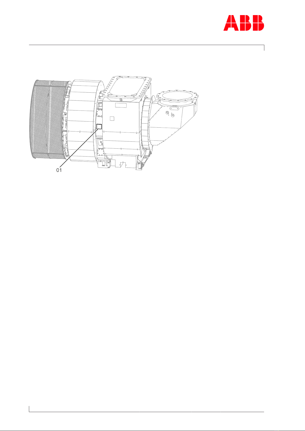
Fig.2: Locations of the rating plates
One rating plate (01) each is attached on the left and the right side of the turbocharger bear-
ing casing.
Page 8 / 141
Questo manuale è adatto per i seguenti modelli
1
Indice
Altri manuali ABB Attrezzature industriali

ABB
ABB HT562794 Manuale utente

ABB
ABB HT573809 Manuale utente

ABB
ABB HT575585 Manuale utente

ABB
ABB HT604063 Manuale utente

ABB
ABB HT567471 Manuale utente

ABB
ABB HT608837 Manuale utente

ABB
ABB HT612543 Manuale utente

ABB
ABB PVI-6000-TL-OUTD-W Manuale utente

ABB
ABB HT580750 Manuale utente

ABB
ABB HT567728 Manuale utente

ABB
ABB HT577985 Manuale utente

ABB
ABB HT566961 Manuale utente

ABB
ABB HT613076 Manuale utente

ABB
ABB HT842357 Manuale utente

ABB
ABB HT570669 Manuale utente

ABB
ABB HT605173 Manuale utente

ABB
ABB HT574306 Manuale utente

ABB
ABB XAC26457 Manuale utente

ABB
ABB HT613682 Manuale utente

ABB
ABB HT573736 Manuale utente


