AeroFlow PERFORMANCE Manuale utente

1 | P a g e
40 Huntingwood Drive Huntingwood NSW 2148
Phone: (02) 8825 1999 Website: www.aeroflowperformance.com
INSTRUCTION MANUAL
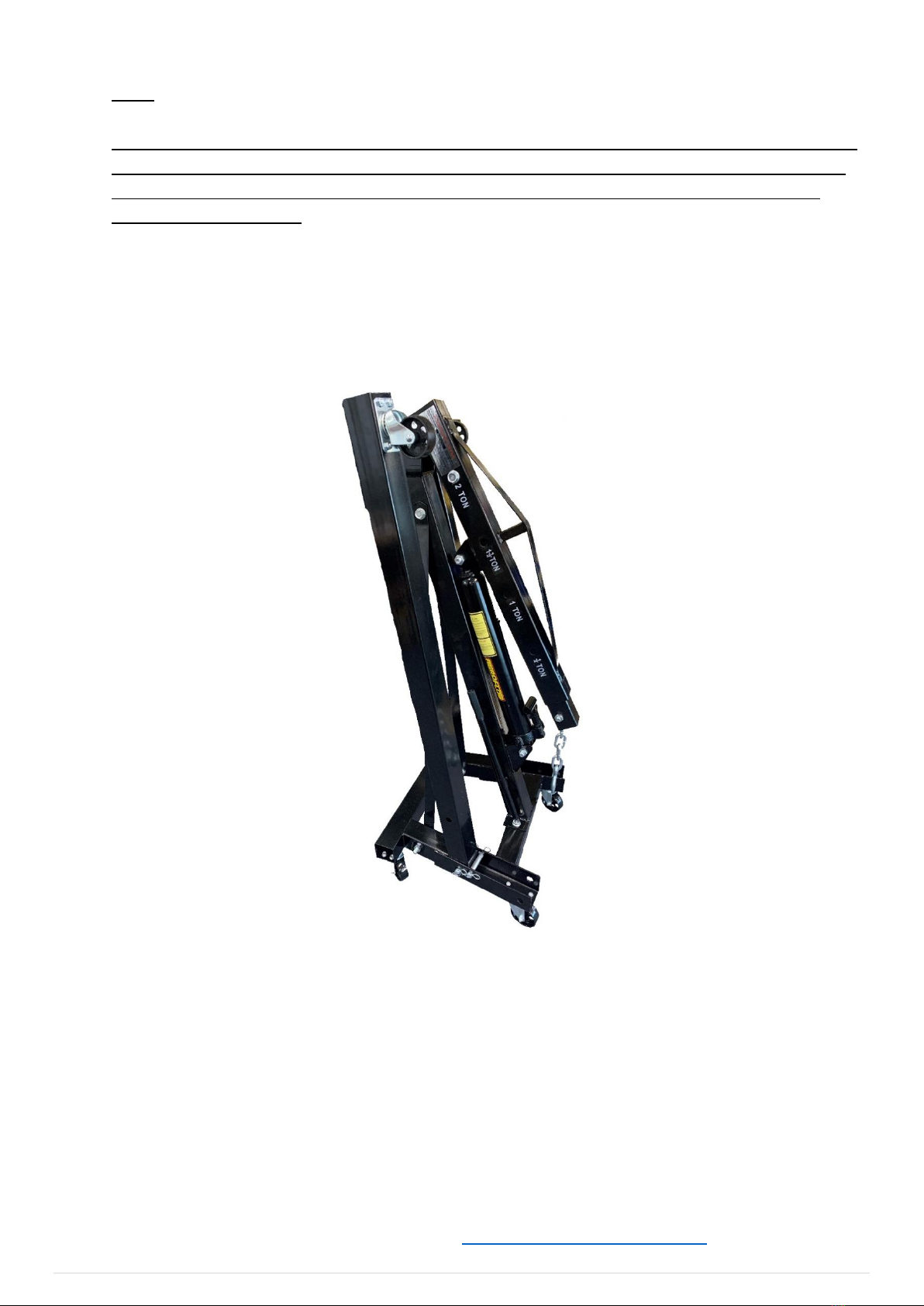
AEROFLOW PERFORMANCE
HEAVY DUTY FOLDABLE ENGINE HOIST
WARNING!
BEFORE PROCEEDING WITH INSTRUCTIONS PLEASE READ CAREFULLY AND UNDERSTAND BEFORE ATTEMPTING TO USE THIS
PRODUCT.
INTRODUCTION
Congratulations on your purchase of the Aeroflow Performance Heavy Duty Foldable Engine Hoist. Aeroflow Performance
products cannot and will not be responsible for any damage, or other conditions resulting from misapplication of the parts
described herein. However, it is our intention to provide the best possible products for our customer, products that perform
properly and satisfy your expectations. Should you have any questions? Please call technical support at +61 2 8825 1900 and
have the product part number on hand when calling.
Got an engine bay which needs to be emptied, this two-tonne professional hydraulic engine crane from Aeroflow Performance
can do the job perfectly. Perfect for use by both professionals and amateur mechanics at the workshop or at home. With an all-
steel, black powder-coated construction and integrated hydraulic ram that can lift up to 2000kg (4409lbs). Featuring a maximum
boom height of 2.3 metres and a reach of 1480mm an engine can be lifted easily out of its bay. Once the engine is free of its
mounts, Six of the 360-degree swivel castor wheels made from robust cast steel allow you to move it easily, and the whole
assembly folds up nice and compact for storage when you’re done.

2 | P a g e
Length of Arm in each position hole:
Position 1 –940mm (37”)
Position 2 –1120mm (44”)
Position 3 –1300mm (51-3/16”)
Position 4 –1480mm (58-17/64”)
Load Rating Specifications for each arm position hole:
Position 1 –2000kg (4409lbs)
Position 2 –1500kg (3306lbs)
Position 3 –1000kg (2204lbs)
Position 4 –500kg (1102lbs)
Maximum Lift Height with arm fully retracted - 1990mm (78-11/32")
Maximum Lift Height with arm fully extended - 2350mm (92-33/64")
DO NOT exceed the maximum capacity for the respective position
Use only on a hard level surface
Never attempt to move when loaded across floors that have cracks or other obstacles which might impede movement of the
wheels
Never work directly under a supported engine
Be sure the engine crane is stable before commencing work
Inspect the crane is in good working condition, not worn, and not missing parts before each use
Do not use when tired and or under the influence of Drugs and Alcohol
Children are not allowed to use. When stored keep out of reach of children
Stay alert. Use caution and common sense when using the Engine Crane
Always check all bolts and moveable parts are secure before lifting engine
Don’t fully tighten bolts until the end
Never attempt to lift an engine with folding legs lifted.
Use with AF98-2064 Engine leveling tool for awkward loads and for greater ease of use
Assistance when assembling is recommended as some parts can be heavy and cumbersome
Failure to follow these instructions and warnings may result in damage to the equipment and or serious personal injury

3 | P a g e
Tools Required: Phillips Head screwdriver, 2x 14mm Spanner or socket, 2x 22mm Spanner or socket, 2x 24 Spanner or socket,
PARTS
NO.
DESCRIPTION
QTY
PARTS
NO.
DESCRIPTION
QTY
1
BASE
1
13
M16(UHL - 110mm) BOLTS
1
2
M14 NUTS
6
14
ARM EXTENSIONS
1
3
PIN
4
15
M12(UHL - 100mm) BOLTS
1
4
M8 (UHL - 16mm) BOLTS
24
16
M16 NUTS
3
5
3.5” SWIVEL WHEELS
4
17
HOOK
1
6
M8 NUTS
24
18
M14 (UHL - 80mm) BOLTS
1
7
LEGS
2
19
HYDRAULIC JACK
1
8
M12 NUTS
1
20
M16 (UHL - 80mm) BOLTS
1
9
PILLAR
1
21
JACK HANDLE
1
10
SUPPORTS
2
22
M16 (UHL - 90mm) BOLTS
1
11
M14 (UHL - 100mm)
BOLTS
5
23
3” SWIVEL WHEELS
2
12
ARM
1

4 | P a g e
INSTRUCTIONS
1. All wheels use M8 bolts and nuts (4-6). Attach a 3.5” swivel wheel (5) to a leg (7), then repeat.
5
7

5 | P a g e
2. With the counter sunk Phillip heads (4-6) attach the 3” swivel wheels (23) to the front of the base
(1).
3. Add the remaining wheels (5) to the rear of the base (1)
5
23
1

6 | P a g e
4. Slide the Legs (7) into the base (1) and lock in place with the Pins (3) and R clips
5. Add the pillar (9) to the base (1) and secure with the hardware (11-2). Don’t fully tighten down as it
may be hard to secure the supports.
9
1
1
7
3
3

7 | P a g e
6. The supports (10) can now be attached to the pillar (9) and base (1) with the hardware (11-2)
7. With hardware (15-8) secure the extendable arm (14) in the main arm (12) at the 2-tonne hole for
assembly and storage.
14
12
10
9

8 | P a g e
8. Lift the main arm (12) into place on the pillar (9) and secure with hardware (13-16)
9. Place the hydraulic jack (19) into the pillar (9) with hardware (22-16). Secure the top of the jack (19)
to the main arm (12) with hardware (20-16).
12
9
19
9
12
22-16

9 | P a g e
10. Slide the hook (17) into the extendable arm (14) via the slot on the underside and lock with
hardware (18-2). Slide the handle (21) in the jack position.
17
14
21
10 | P a g e
NOTE
SOMETIMES, DURING SHIPMENT AND HANDLING, AIR GETS INTO THE HYDRAULIC SYSTEM, WHICH
MAY CAUSE POOR LIFTING PERFORMANCE. PURGE ANY AIR IN THE HYDRAULIC SYSTEM BY FULLY
OPENING RELEASE VALVE (TURN VALVE COUNTER-CLOCKWISE) AND OPERATE PUMP HANDLE
RAPIDLY SEVERAL TIMES.
11. To store the crane, make sure the extendable arm is pushed in and secured at the 2-tonne hole.
Then let down the hydraulic jack (19) and place the handle in the holder on the pillar (9). Take out
the front locking pins on the legs (7). Lift them up and re insert the locking pins in the locking holes.
For more information or technical enquires
Contact: Aeroflow Performance on
Phone: (02) 8825 1979 Website: www.aeroflowperformance.com
Indice
Altri manuali AeroFlow Paranco a catena

Manuali Paranco a catena popolari di altre marche

EINHELL
EINHELL Herkules H-F 1000 Manuale utente

RED ROOSTER
RED ROOSTER TCR-250 Manuale utente

POWERTEX
POWERTEX PCB-S1 Manuale utente

Parkside
Parkside PSZ 250 A1 Manuale utente

Ingersoll-Rand
Ingersoll-Rand QCH Series Manuale utente

Creative Conners
Creative Conners CM Varistar Smart Chain Hoist Manuale utente


