Aiphone IS-IPRY Manuale del proprietario

IS-IPRY
Programming Manual
For use with IX Series & IS-IP Series
1016
Input/Output Network Adaptor

• IS-IPRY
• Programming Manual
• 6 Screw Terminal Blocks
• MAC Address Label
Overview / Description
2
Package Contents
The IS-IPRY is a Barix Barionet 50 with proprietary rmware installed for the device to function with the Aiphone IX
Series, IS-IP Series stations,
Relay outputs can be programmed to trigger for door release, upon call-in, while in communication, or while calling
and communicating.
The IS-IPRY is required when running IX Mobile app on a mobile device. The IS-IPRY will function as the IX Series
app server. Up to 8 mobile devices can be employed per server. The IS-IPRY will alert the mobile device if it goes out
of wireless network range.
If only using the IS-IPRY for IX Mobile, congure the adaptor as shown on page 5 then skip to page 10 (IX Mobile
Server). The SIF.ini le is not needed when only using the adaptor as the IX Server. Refer to pages 10-14 for steps on
adding a mobile device to the IX Series using the IX Support Tool and for setting up the mobile device.
SIF.ini File (IX Series and IS-IP Series Stations Only)
Create a SIF.ini file in order for the IX Series and IS-IP Series door stations and master stations to communicate with the
adaptor. Use a text editor program (i.e. notepad) to create this file and save it with a .ini extension.
Program Type: Range is between 0100 and 1111 (Binary).
IS-IPRY IP Address:
IP address assigned to the IS-IPRY. Must be unique for each IS-IPRY.
Destination Port:
Port number assigned on the IS-IPRY. The default port is 10000. This can be
set in the range from 1 to 65535.
SSL Y/N :
This device does not use SSL. Input 0 for no.
Example Text File: 0100,192.168.1.45,10000,0
Save the SIF le with a .ini extension (.ini must be typed manually) to a location on the PC being used for programming the IX
Series or IS-IP Series stations. This le must be uploaded to each device associated with the IS-IPRY using the instructions
that follow.
Program
Type
IS-IPRY
IP Address
Destination
Port
SSL
Y/N
Important:
The intercom system must be fully programmed and operational prior to programming the IS-IPRY adaptor.

3
IX Series: Uploading SIF.ini File
A. Log in to the IX Series system using the IX Support Tool.
B. Expand the Function Settings tree on the left and select SIF Integration.
C.
Choose the station to be edited from the Number drop down menu then click the Select button.
D. Select the Enable radio button for both the CGI Integration and SIF Integration.
Click Browse to browse to where the .ini le is saved and click Upload to send to station.
E. Click Update to save the changes for the station then repeat the process for each station that will be associated
with the IS-IPRY.
F. After completing steps C, D, and E for each station, upload the changes. Click File, Upload Settings to Station.
Select the stations to upload to and click Start Upload.
Upload the SIF.ini le to each IX Series station associated with the IS-IPRY adaptor.
! The IX Support Tool or web browser interface can be used to upload the SIF.ini le to each station.
Loading via the IX Support Tool is shown in these instructions.
Important:
The intercom system must be fully programmed and operational prior to uploading the SIF.ini le.

4
IS-IP Series: Uploading SIF.ini File
Upload the SIF.ini le to each IS-IP Series station associated with the IS-IPRY adaptor.
! Note that the IP address for each station will be unique for your network settings.
Important:
The intercom system must be fully programmed and operational prior to uploading the SIF.ini le.
A. Open a web browser and type https://[ip address]/sif in the address bar.
[ip address] = static IP address assigned to the station being programmed.
B. A security certicate error message will appear. Continue to the website.
C. Enter the administrator ID and password.
Default ID: aiphone
Default Password: aiphone
D.
Select Transmission setting under Uploading SIF setting data from the menu on the left side of the screen.
E. Click the Upload button. A new window will open.
F. Click the Browse button and navigate to the .ini le saved on the PC.
G. Click the Upload button. A message will appear stating the settings will not be applied until the system is updated.
H. Click Updating the system from the menu on the left. Click the Update button and the unit will update and restart
itself.
I. Repeat this process for each door and master station associated with the IS-IPRY adaptor.
5
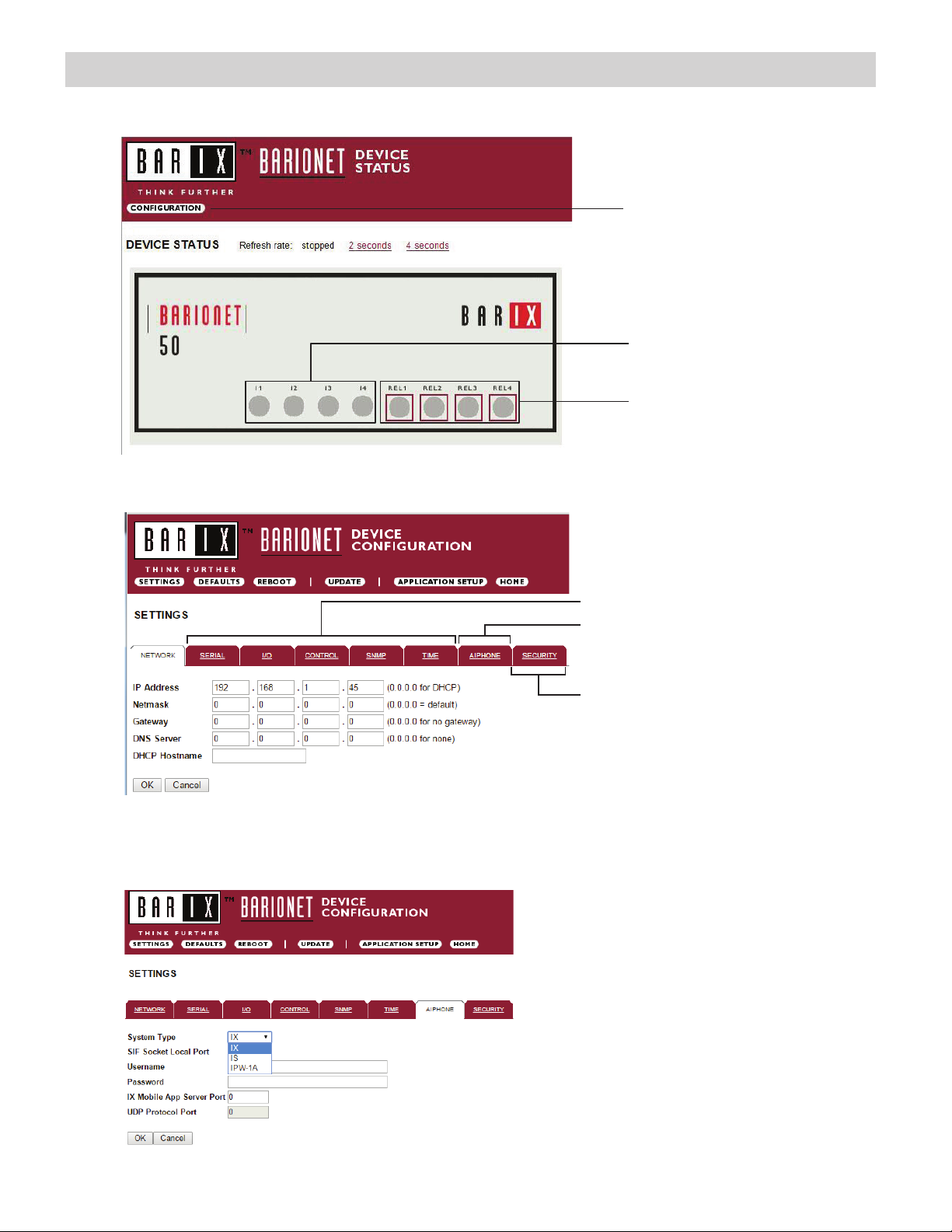
Conguring the IS-IPRY (assigning IP address and system use)
Relay status and control.
Click on each LED to verify
relay function.
Digital input status
Conguration button
The IS-IPRY has a default IP address of 192.168.1.45. Open a web browser and point the address bar to
http://192.168.1.45 for access to the adaptor. The rst screen to appear will be the Device Status screen.
Click the CONFIGURATION button to open the Device Conguration screen. This is where a unique IP Address,
Netmask, and Gateway can be assigned to the adaptor. Consult with your IT department for these settings.
Settings not utilized for Aiphone
functionality. Do not adjust.
SECURITY: For creating a password for
access to the web browser interface.
AIPHONE: Select the Aiphone system
type the relay is to be used with.
The Aiphone system type that the relay is being integrated with will need to be selected. Click the AIPHONE tab. Use the
drop down by System Type to select the appropriate system. Once selected, click OK. Click Reboot on the next screen to
restart the adaptor.
System Type: Select IX or IS
SIF Socket Local Port: Enter the port number
that was assigned in the SIF.ini le. Leave at “0”
to use default 10000 port.
Username & Password: For IX/IS, enter
system’s username and password. Leave blank if
using default (IX = admin, IS = aiphone).
IX Mobile App Server Port: Enter the port number
that has been assigned in the IX Mobile app(s).
Enter “0” if default port (5061) is to be used.
.
Note: If the IP Adress is unknown or lost, Please remove the cover and place a shunt on J9 during 10 sec on the PCB

6
The IS-IPRY has 4 relays that can be programmed to trigger while calling, while in communication, or while calling and
communicating with a specic station. The relays can also be programmed for door release.
Set the IS-IPRY for use with the IX Series (refer to page 5).
From the DEVICE CONFIGURATION screen, click APPLICATION SETUP.
APPLICATION SETUP button
Enter the station number of the station to be associated with the relay. Select the relay condition from the Relay Action
drop down menu.
Click on Apply Settings then click Reboot to restart the adaptor with the saved changes.
When the entered station is active, the associated relay will trigger based on the Relay Action settings.
Relay Action options:
• Door Release - Normally-Open
• Door Release - Normally-Closed
• Active while Calling from Source
• Active while Communicating
• Active during Calling and Communicating
The IX Series allows for door release partitioning. When the IS-IPRY relay action is set for door release, the relay
will be triggered only if door release is allowed on the station. To set door release partitioning, refer to Door Release
Settings under the Function Settings tree in the IX Support Tool.
When the relay action is set for the “Door Release” options, the relay on the IS-IPRY will trigger when the associated
station is calling or communicating and its door release contact is triggered.
When the relay action is set for any of the “Active While” options, the relay will trigger when the associated station calls
or communicates at any priority level.
Relay will trigger when the associated station’s door release contact is triggered.
Relay will trigger when the associated station calls or communicates.
}
}
IX Series: Relay Output Programming

7
IX Series: Input Programming
The IS-IPRY adaptor has 4 inputs that can be programmed to trigger a call-in from a specic door station or master station to a
specic master station or group of master stations.
The IS-IPRY inputs can have different calling rules than the default calling rule set during the IX Series programming.
Select the call-in priority level for each input using the Priority drop down menu.
Enter the target IP address of the station for remote call-in.
Click Apply Settings to save the changes. Do not reboot the adaptor at this time.
Click APPLICATION SETUP to return to the Application Conguration Screen.
Click on Destinations next to the input being congured. Another window will open. Enter the station number of the
master stations to be called when the input is triggered.
When the target IP address is a door station, a maximum of 20 master stations can be entered.
When the target IP address is a master station, a maximum of 20 master stations or 1 group can be entered. A group can
consist of up to 50 master stations and must be created using the IX Support Tool.
Check the Enable box beside each station entered.
Click on Apply Settings then click Reboot to restart the adaptor with the changes.
The IS-IPRY has 4 relays that can be programmed to trigger when a specic door station is calling, while in
communication, or while calling and communicating. The relays can also be programmed for door release from one or
multiple IP master station(s).
Set the IS-IPRY for use with the IS-IP Series (refer to page 5).
From the Device Conguration screen, click APPLICATION SETUP.
Application Setup button
IS-IP Series: Relay Output Programming

8
Linked Stations Table:
Enter the IP address and TermID for each IS-IP station in the IS conguration. This table is used as a reference for
each TermID in the system. After inputting each IP address and TermID, click Apply Settings at the bottom of the
page to save the settings to memory. Return to the Application Screen or reboot adaptor by clicking the Reboot button.
Rebooting must occur to update adaptor settings.
A TermID identies the location of an IS-IP station in the IS Series conguration. It also distinguishes between master
stations and door stations. A master station TermID will be xx-001 and a door station TermID will be xx-101. “xx”
represents the line in which the station resides under “IP Unit Registration” in the IS Host programming.
Example:
01-101: Door station in address location 1.
03-001: Master station in address location 3.
Denition: TermID
Relay Functionality:
Enter the TermID for the door station to be associated to the relay.
Select the relay action from the drop down menu.
Relay Action options:
• Door Release - Normally-Open
• Door Release - Normally-Closed
• Active while Calling from source
• Active while in Communication with source
• Active during Calling and Communication
Relay will trigger when a congured master station pushes the door release button
for the associated door.
Relay will trigger when the associated door station calls or communicates.
}
}
IS-IP Series: Relay Output Programming (cont.)

9
When the relay action is set for the “Door Release” options, the relay will trigger when the associated door station is in
communication, but only when a “congured” master station pushes the door release button.
When the relay action is set for any of the “Active While” options, the relay will trigger when the associated door station
calls or communicates at any priority level.
After the Door TermID and Relay Action has been set, click Apply Settings at the bottom of the screen to save the
settings to memory. Return to the Application Screen or reboot adaptor by clicking on the Reboot button. Rebooting
must occur to update adaptor settings.
To program a master station to control door release, click on the Congure button. A new window will open and the
table shown below will be populated based on the entries made in the Linked Stations Table (see page 8). Check
the Flag box beside each master station that will be “allowed” to trigger this relay for door release. Once all master
stations have been checked, click Apply Settings at the bottom of this window to save the settings to memory.
Reboot to update adaptor settings.
Note: The IS-SOFT software masters stations can NOT be enabled for door release using the IS-IPRY.
IS-IP Series: Input Programming
The IS-IPRY adaptor has 4 inputs that can be programmed to trigger a call-in from a specic door station to a specic
master station or group of master stations (max. 20). The IS-IPRY inputs can have different calling rules than the default
calling rule set under Advanced Station Settings in the IS Host Programming.
Choose the Call-In priority level for each input using the Priority drop down menu. Enter the target IP address of the
door station for remote call-in.
Click Apply Settings to save the changes. Do not reboot the adaptor at this time.
Click APPLICATION SETUP to return to the Application Conguration screen.

10
IS-IP Series: Input Programming (cont.)
Click on Destinations next to the input being congured. A new window will open. Enter the TermID for each master
station to be called (see page 8 for TermID information). A maximum of 20 master stations TermID’s can be entered.
Check the Enable box beside each TermID entered to allow the master to be called. Once all master station TermID’s
have been entered and enabled, click Apply Settings at the bottom of this window to save the settings to memory.
Reboot to update adaptor settings.
IX Mobile Server
The IS-IPRY adaptor is used as a server for up to 8 mobile devices when using IX Mobile.
Set the IS-IPRY for use with the IX Series (refer to page 5).
Enter the IP address for each of the mobile devices in the IX Mobile Server Functionality table.
Click on Apply Settings then click Reboot to restart the adaptor with the changes.
Refer to pages 12-15 for steps on adding a mobile device to the IX system using the IX Support Tool and for setting
up the mobile device.
The IX Mobile app turns an iPhone®, iPad®, or iPod touch® running Apple® iOS versions 8.0 or higher or mobile
devices running Android™ 4.1 or higher into an IX Series sub master station. Follow the steps below to congure the
IX Series system and to prepare the mobile device(s) for connection via WiFi or over a cellular network with a VPN
connection. Please note the mobile device running the IX Mobile app and the IX Series system must be connected to
the same network.
Important:
IX-Mobile
- An IX-MV master station and an IS-IPRY adaptor are required in the system for the IX Mobile App to work -
- The IX Series hardware devices must be programmed and operational prior to adding the IX Mobile device -
Indice
Altri manuali Aiphone Ricevitore

Aiphone
Aiphone RY-IP44 Manuale del proprietario

Aiphone
Aiphone MC-A/A Manuale utente

Aiphone
Aiphone SKK-620C Manuale utente

Aiphone
Aiphone MYW-BA Manuale utente

Aiphone
Aiphone DAK-2S Manuale utente

Aiphone
Aiphone IXW-MA Manuale utente

Aiphone
Aiphone MYW-BA Manuale utente

Aiphone
Aiphone MYW-MD Manuale utente

Aiphone
Aiphone LEF Series Manuale utente

Aiphone
Aiphone MYW-BA Manuale utente

Aiphone
Aiphone MYW-BA Manuale utente

Aiphone
Aiphone AXW-AVR Manuale utente

Aiphone
Aiphone PS-12F Manuale utente

Aiphone
Aiphone KCS-IFA Manuale utente

Aiphone
Aiphone NB-U Manuale utente

Aiphone
Aiphone TD-H Series Manuale utente

Aiphone
Aiphone KCW-D/B Manuale utente

Aiphone
Aiphone RY-3DL Manuale utente

Aiphone
Aiphone MYW-BA-M Manuale utente


