
Air Lift LoadLifter 5000 Ultimate Manuale utente

For maximum effectiveness and
safety, please read these instructions
completely before proceeding with
installation.
Failure to read these instructions can result in an
incorrect installation.
MN-857 • (021306) • ECR 7682
INSTALLATION GUIDE
ADJUSTABLE AIR HELPER SPRINGS
TOW AND HAUL WITH SAFETY AND COMFORTTM
Kit Number
88202


1
MN-857
LoadLifter 5000 Ultimate
Introduction............................................. 2
Important Safety Notice ................................................2
Notation Explanation ...................................................2
Installation Diagram ...................................... 3
Hardware List ........................................................4
Installing the LoadLifter 5000 Ultimate System ............... 4
Getting Started .......................................................4
Assembling the Air Spring ...............................................5
Attaching the Lower Bracket .............................................5
Attaching the Upper Bracket .............................................5
Securing the Air Spring to the Brackets. . . . . . . . . . . . . . . . . . . . . . . . . . . . . . . . . . . . . 7
Relocating the Jounce Bumper ...........................................7
Installing the Air Lines ..................................................8
Checking For Leaks. . . . . . . . . . . . . . . . . . . . . . . . . . . . . . . . . . . . . . . . . . . . . . . . . . . . 9
Fixing Leaks .........................................................9
Before Operating ........................................11
Installation Checklist ...................................................11
Post-Installation Checklist ...............................................11
Product Use, Maintenance and Servicing ...................12
Minimum and Maximum Pressure.........................................12
Maintenance Guidelines ................................................12
Troubleshooting Guide .................................................12
Frequently Asked Questions .............................................13
Tuning the Air Pressure.................................................13
Guidelines for Adding Air................................................14
Choosing the Right On-Board Air Compressor System .......15
Limited Warranty and Return Policy ........................16
Replacement Information .................................17
Contact Information ......................................17
TABLE OF CONTENTS

2MN-857
LoadLifter 5000 Ultimate
Introduction
The purpose of this publication is to assist with the installation, maintenance and
troubleshooting of the LoadLifter 5000 Ultimate air spring kit. LoadLifter 5000 Ultimate
utilizes sturdy, reinforced, commercial grade single or double, depending on the kit, convolute
bellows. The bellows are manufactured like a tire with layers of rubber and cords that
control growth. An internal jounce bumper inside the spring absorbs shock and eliminates
harsh jarring on rough roads. The internal jounce bumper replaces the factory bumper and
allows the air springs to safely be run at zero air pressure. LoadLifter 5000 Ultimate kits
are recommended for most 3/4 and 1 ton pickups and SUVs with leaf springs and provide
up to 5,000 lbs. of load leveling support with air adjustability from 5-100 PSI. The kits are
also used in motorhome rear kits and some motorhome fronts where leaf springs are used.
It is important to read and understand the entire installation guide before beginning installation
or performing any maintenance, service or repair. The information here includes a hardware
list, tool list, step-by-step installation information, maintenance tips, safety information and
a troubleshooting guide.
Air Lift Company reserves the right to make changes and improvements to its products and
publications at any time. For the latest version of this manual, contact Air Lift Company at
(800) 248-0892 or visit our website at www.airliftcompany.com.
IMPORTANT SAFETY NOTICE
The installation of this kit does not alter the Gross Vehicle Weight Rating (GVWR) or payload
of the vehicle. Check your vehicle’s owner’s manual and do not exceed the maximum load
listed for your vehicle.
Gross Vehicle Weight Rating: The maximum allowable weight of the fully loaded vehicle
(including passengers and cargo). This number — along with other weight limits, as well
as tire, rim size and ination pressure data — is shown on the vehicle’s Safety Compliance
Certication Label.
Payload: The combined, maximum allowable weight of cargo and passengers that the
vehicle is designed to carry. Payload is GVWR minus the Base Curb Weight.
NOTATION EXPLANATION
Hazard notations appear in various locations in this publication. Information which is
highlighted by one of these notations must be observed to help minimize risk of personal
injury or possible improper installation which may render the vehicle unsafe. Notes are used
to help emphasize areas of procedural importance and provide helpful suggestions. The
following denitions explain the use of these notations as they appear throughout this guide.
INDICATES IMMEDIATE HAZARDS WHICH WILL RESULT IN SEVERE PERSONAL
INJURY OR DEATH.
INDICATES HAZARDS OR UNSAFE PRACTICES WHICH COULD RESULT IN SEVERE
PERSONAL INJURY OR DEATH.
INDICATES HAZARDS OR UNSAFE PRACTICES WHICH COULD RESULT IN DAMAGE
TO THE MACHINE OR MINOR PERSONAL INJURY.
Indicates a procedure, practice or hint which is important to highlight.
DANGER
NOTE
WARNING
CAUTION
3
MN-857
LoadLifter 5000 Ultimate
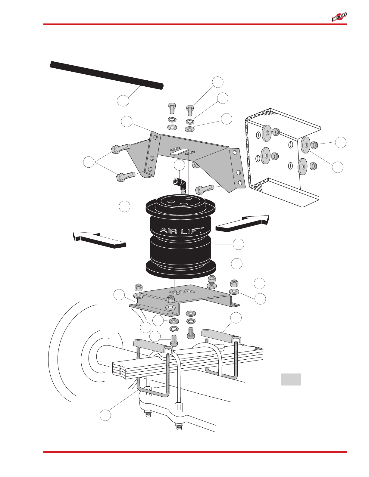
Installation Diagram
M
F
G
J
L
IH
Forward
Outboard
L
I
H
B
K
AA
E
C
D
D
A
G
H
g. 1
4MN-857
LoadLifter 5000 Ultimate
Installing the LoadLifter 5000 Ultimate System
DANGER
Item P/N Description...............................Qty
A 58496 Bellow ................................................... 2
B 07475 Upper Bracket....................................... 2
C 03102 Lower Bracket....................................... 2
D 11967 Roll Plate............................................... 4
E 21837 Elbow Fitting ......................................... 2
F 10583 4.5” U-Bolt............................................. 4
G 18435 3/8” Nylock Nut .................................... 16
H 18444 3/8” Flat Washer .................................. 16
I 18427 3/8” Lock Washer.................................. 8
J 18447 3/8” Large Flat Washer ......................... 8
K 17159 3/8” x 1.5” HWH Bolt............................. 8
L 17203 3/8” x 7/8” HH Bolt..................................... 8
Item P/N Description..................................Qty
M01426 3” Spacer Bar........................................ 4
Air Line Assembly Parts
AA 20086 Air Line Assembly ................................. 1
BB 10466 Tie Strap*.............................................. 6
CC 21230 Valve Caps* .......................................... 2
DD 18405 5/16” Flat Washer*................................ 2
EE 21234 Rubber Washer* ................................... 2
FF 18411 mall Star Washer* ................................. 2
GG 21233 5/16” Hex Nut* ...................................... 4
(*not shown in Figure 1)
HARDWARE LIST
Missing or damaged parts? Call Air Lift customer
service at (800) 248-0892 for a replacement part.
STOP!
COMPRESSED AIR CAN CAUSE INJURY AND DAMAGE TO THE VEHICLE AND
PARTS IF IT IS NOT HANDLED PROPERLY. FOR YOUR SAFETY, DO NOT
TRY TO INFLATE THE AIR SPRINGS UNTIL THEY HAVE BEEN PROPERLY
SECURED TO THE VEHICLE.
GETTING STARTED
1. Raise the vehicle, remove the wheels, and support the axle with jackstands. Obtain the
normal ride height.
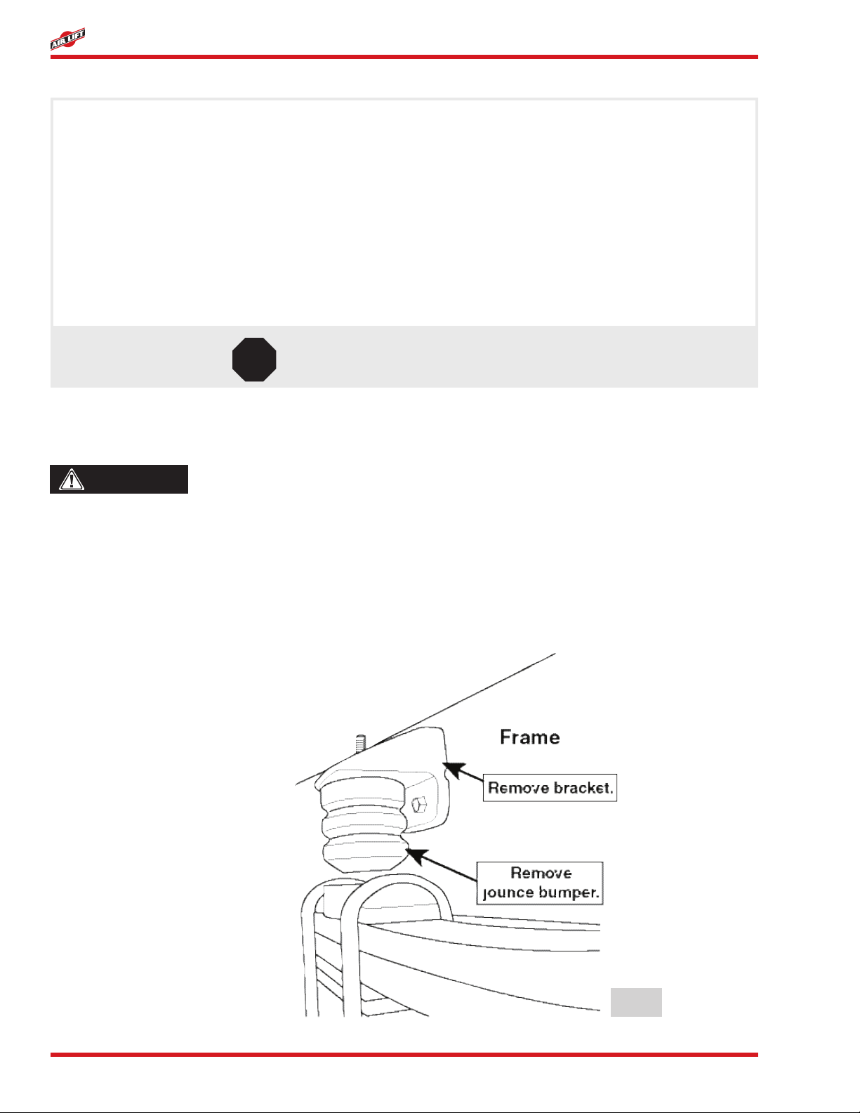
2. Remove the jounce bumper and bracket from the side of the frame above the leaf spring
(Figure 2).
g. 2

5
MN-857
LoadLifter 5000 Ultimate
ASSEMBLING THE AIR SPRING
1. Set a roll plate (D) on both ends of the air spring (A). The radiused (rounded) edge of
the roll plate will be towards the air spring so that the air spring is seated in both roll
plates (Figure 1).
2. Install a 90° swivel air tting (E) nger tight plus 11/2 “ turns (Figure 1). Do not overtighten.
3. Place the upper bracket (B) onto the top of the bellow and roll plate with the legs facing
down.
4. Set the air spring on the lower bracket (C) aligning the two holes in the base of the air
spring with the two outer slots in the top of the lower bracket (Figure 1).
5. Loosely attach the upper bracket to the assembly using at washers (H), lock washers
(I), and hex head bolts (L). Remember that the legs face down (Figure 1).
6. Loosely attach the lower bracket to the assembly using at washers (H), lock washers
(I), and hex head bolts (L). See Figure 1.
ATTACHING THE LOWER BRACKET
1. Set the assembly over the center spring retainer. Install two spacers (M) between the
lower bracket and the spring (Figure 1).
2. Bolt the lower bracket (C) to the spring using two U-bolts (F), four at washers (H) and
four nyloc nuts (G) (Figure 5). Torque to 16 ft.lbs.
3. Trim the inside U-bolt if necessary to keep the bolt from hitting the upper bracket (Figure
3).
g. 3
ATTACHING THE UPPER BRACKET
BEFORE DRILLING, CHECK THE BACK-SIDE OF THE FRAME FOR CLEARANCE ISSUES
WITH THE BRAKE LINES, GAS LINES, AND ELECTRICAL LINES. ANY OBSTACLES
WILL NEED TO BE TEMPORARILY RELOCATED TO CLEAR THE AREA.
1. Position the upper bracket (B) so that it is parallel with the lower bracket and align the
assembly vertically and horizontally.
CAUTION

6MN-857
LoadLifter 5000 Ultimate
Mount the upper bracket as high on the frame as possible. There should be a minimum of 6
inches between the upper and lower brackets (Figure 4). The top two holes may be above
or even with the frame. If this is the case, use the two lower holes in the upper bracket for
mounting.
2. Using the upper bracket as a template, center punch and drill one 3/8” locator hole through
the frame (Figure 1).
3. Attach a hex washer head frame bolt (K), oversize washer (J) and nyloc nut (G). Do not
overtighten. Adjust both sides, X and Y, so that they are the same (Figure 5).
4. Drill the remaining holes. Install the appropriate hardware and torque the nuts to 44
ft.lbs.
g. 4
g. 5
NOTE

7
MN-857
LoadLifter 5000 Ultimate
g. 6
SECURING THE AIR SPRING TO THE BRACKETS
1. Align the bellows (A) in and out so that they are perpendicular to the upper and lower
brackets (Figure 5).
Keep a nger’s width between the roll plate (D) and frame (Figure 6).
2. Tighten both upper and lower bellows mounting bolts. Torque to a maximum of 20 ft.lbs.
NOTE
RELOCATING THE JOUNCE BUMPER
1. The jounce bumper must be relocated under the frame above the axle. First, remove
the jounce bumper from the stock bracket.
2. Drill a 3/8” hole above the axle, in the bottom of the frame ange (Figure 7).
g. 7

8MN-857
LoadLifter 5000 Ultimate
g. 9
3. Mount the jounce bumper under the frame using O.E.M. hardware. Tighten securely
(Figure 8).
Drop the axle slightly if necessary to position the jounce bumper between the frame and
axle (Figure 8).
NOTE
NOTE
g. 8
INSTALLING THE AIR LINES
When installing the air lines, there must be at least six inches of clearance between the air
lines and any heat sources.
1. Choose a convenient location for mounting the ination valves. Popular locations for the
ination valve are:
The wheel well anges; The license plate recess in bumper; Under the gas cap access
door; Through license plate (Figure 11).
Whatever the chosen location is, make sure there is enough clearance around the ination
valves for an air chuck.
2. Drill a 5/16 “ hole to install the ination valves.
3. Cut the air line assembly (AA) in two equal lengths.
WHEN CUTTING OR TRIMMING THE AIR LINE, USE A HOSE CUTTER (AIR LIFT P/N
10530), A RAZOR BLADE OR A SHARP KNIFE. A CLEAN, SQUARE CUT WILL ENSURE
AGAINST LEAKS. DO NOT USE WIRE CUTTERS OR SCISSORS TO CUT THE AIR
LINE. THESE TOOLS MAY FLATTEN OR CRIMP THE AIR LINE CAUSING IT TO LEAK
AROUND THE O-RING SEAL INSIDE THE ELBOW FITTING (FIGURE 9).
NOTE
CAUTION
Altri manuali per LoadLifter 5000 Ultimate
7
Questo manuale è adatto per i seguenti modelli
1
Indice
Altri manuali Air Lift Sistema di sollevamento


Manuali Sistema di sollevamento popolari di altre marche


Genie
Genie Z-60/34 Manuale utente

Screen Technics
Screen Technics INTERFIT Vertical Up Lift Manuale utente

Mortuary Lift
Mortuary Lift ULTIMATE 1000 Manuale utente

Custom Equipment
Custom Equipment Hy-Brid 3 Series Manuale di programmazione

Custom Equipment
Custom Equipment Hy-Brid Lifts 2 Series Manuale di programmazione

Hy-Brid Lifts
Hy-Brid Lifts HB-P3.6 Manuale di programmazione


