Aircatglobal VirtualFly SOLO-G1 Manuale utente

SOLO G1
USER'S MANUAL
Rev. .
February
FOR Cessna C172SP Skyhawk, Cessna Skylane II RG R182
and Cessna T206
FOR
N3 06 0E 120 150
STEE R
FOR
S2 10 240W 3003 30
STEE R
ON NO
RADI O


3
SOLO-G1 USER'S MANUAL
TABLE OF
CONTENTS
. IDENTIFICATION OF ELEMENTS
. INSTALLATION
.. CABLE CONNECTION
.. INSTALATION OF FILES TO THE COMPUTER
OF MFS/PD.
.. VF-COMPASS, YOKO & VRNIO FLIGHT
CONTROLS CONFIGURATION
. START-UP THE SOLO-G
. SELECTION OF PANEL TYPE
. GLASS-COCKPIT VF-G
.. INTRODUCTION
.. PFD/MFD CONTROLS
. MULTIPLE SOLOFLIGHTPANEL OR MULTIPLE
MFS/PD COMPUTER ON THE SAME NETWORK
. TROUBLESHOOTING
.. ANOMALY: The "VFConnect" pluggin in MFS/PD
computer displays “Connection Status: Searching…”
.. ANOMALY: Connection goes down, is intermittent or
indicators moves sharply
. TECHNICAL FEATURES
. REMOTE ASSISTANCE

41. IDENTIFICATION OF ELEMENTS - SOLO-G1 USER'S MANUAL
1. IDENTIFICATION OF
ELEMENTS
Packaging contents:
. SOLO-G panel ( unit).
. SOLO-G Electrical power cable ( unit).
. SOLO-G Network cable ( unit).
. YOKO+ “the yoke” USB cable ( unit) (male, male A-B).
. VRNIO “TPM” USB cable ( unit) (male, male A-A).
. SOLO-G Memory Stick (unit).
Content: SOLO-G1_User's Manual, VF-TestCalibrate-S, VFConnect,
G1000_Network_Module, Garmin G1000 manual (G1000_
CessnaNavIII_PilotsGuide.pdf), FSUIPC, TeamViewer, Aircraft-Flight
Models folder.
. VF-Compass ( unit).
. SOLO-G Quick Start Guide ( unit).
. SOLO-G User's Manual ( unit).
. Carenado Cessna Invoice license ( unit).
It is important to save all parts you are not going to use, in case you need
them in the future.
-
FO R
N3 06 0E 120 150
ST EE R
FO R
S2 10 240W 3003 30
STEE R
ON NO
RADI O

5
2. INSTALLATION - SOLO-G1 USER'S MANUAL
2. INSTALLATION
The SOLO-G, has been technologically developed to be fully
plug&play. It connects easily to any computer running the “Microsoft
Flight Simulator” or “PreparD” hereinafter referred to as “MFS/PD”.
Still, we’ll give you a series of steps to follow to install your panel.
The user must consider that SOLO-G has important modules:
• Thepanelitself:switches,STBYgauges
• VF-Compass
• YOKO+“Theyoke”.
• V3rnioTPM“Throtlle,propeller,andmixture”
• TheG1000GlassCockpit
To activate all panel modules, the user must undertake operations:
• Cableconnection
• InstalationoflesinthecomputerofMFS/P3D
• VF-Compass,YOKO+andV3RNIOightcontrolsconguration.
.. CABLE CONNECTION
Attention: before starting, the red back switch must be in o.
Please, stick the VF-Compass on top of the SOLO-G (the foot sup-
port has magnets to stick it).
The user has options to connect the network cable:
• Direct(option1).
• Throughlannetwork(option2).
Onceyounish,yourmustconnecttheCable2toapowersocket.
MFS/PD computer
MFS/PD computer
Once you finish, your must to connect the Cable to a power socket.
Home router
Switch OFF
Switch OFF
OPTION : Direct
OPTION : Through LAN Network
Cable
Cable
Cable
Cable
Cable
Cable
Cable Cable
Not supplied
cable
FOR
N3 06 0E 120 150
STEE R
FOR
S2 10 240W 3003 30
STEE R
ON NO
RADI O
FOR
N3 06 0E 120 150
STEE R
FOR
S2 10 240W 3003 30
STEE R
ON NO
RADI O

62. INSTALLATION - SOLO-G1 USER'S MANUAL
.. INSTALLATION OF FILES TO THE COMPUTER OF MFS/PD
FSUIPC Installation
In case you already have FSUIPC installed in your MFS/PreparD you
can skip this step.
• Go to the “FSUIPC” folder from the memory stick provided with
SOLO-G.
• Execute the setup program according to your MFS version ("FSX-
PreparD v-" or "Prepard v-").
• When the installer ask about registering, Click on “Not now”.
VFCONNECT Installation
Copy the "VFConnect.exe" file from the Memory Stick provided with
SOLO-G, in the MFS/PD desktop computer.
As "VFConnect” communication module receives input data from MFS/
PD and then send it to SOLO-G, Keep in mind, that "VFConnect.exe”
has to remain ON when you use the SOLO-G.
“VF-Test&Calibrate-S-S” Control Panel Installation
Copy the “VF-TestCalibrate.exe” file from the Memory Stick provided
with SOLO-G, in the MFS/PD desktop computer.
G1000 Network Module Installation
In case you have MFS/PreparD or others softwares running, you have
to close them before the G Network Module installation.
• Go to the memory stick provided with SOLO-G.
• Execute the G_network_module.exe setup program and follow
the installation wizard.
AIRCRAFT-FLIGHT MODEL installation
The SOLO-G panel can only works with the AIRCRAFT provided
in the memory Stick, please see the Aircraft-Flight Models folder. You
have to install these aircraft provided in your MFS-PreparD compu-
ter and load one of them to operate with the SOLO G panel.
To install the Aircraft follow these instructions:
• Go to the FSX-PreparD installation root folder. Default locations are:
-"C:\Program Files (x)\Microsoft Games\Microsoft Flight Simulator X"
-"C:\Program Files (x)\Lockheed Martin\PreparD v"
-"C:\Program Files\Lockheed Martin\PreparD v"
• Enter in "SimObjects" folder and then "Airplanes".
• Place the C/C/C Aircraft folders from the memory stick
inside the "Airplanes" folder.

7
2. INSTALLATION - SOLO-G1 USER'S MANUAL
V3RNIO
Configuration Using VF-Test&Calibrate-S
• Disable "VirtualFly - TPM VRNIO" assignments on MFS/PD "Button
and keys" tab and "Axes" tab.
• Just double click on the "VF-Test&Calibrate-S.exe" file to execute it.
• Go to "TQ/VRNIO" tab and select the VRNIO device from the "Se-
lect device:" list.
• Click on "Save Current Configuration" button.
• In "TQ/VRNIO" tab you can test the device.
VF-COMPASS
Configuration Using VF-Test&Calibrate-S
• Just double click on the "VF-Test&Calibrate.exe" file to execute it.
• Go to "VF-COMPASS" tab and select the VF-COMPASS device from
the "Select device:" list.
• Click on "Save Current Configuration" button.
• In "VF-COMPASS" tab you can control the backlight and test the device.
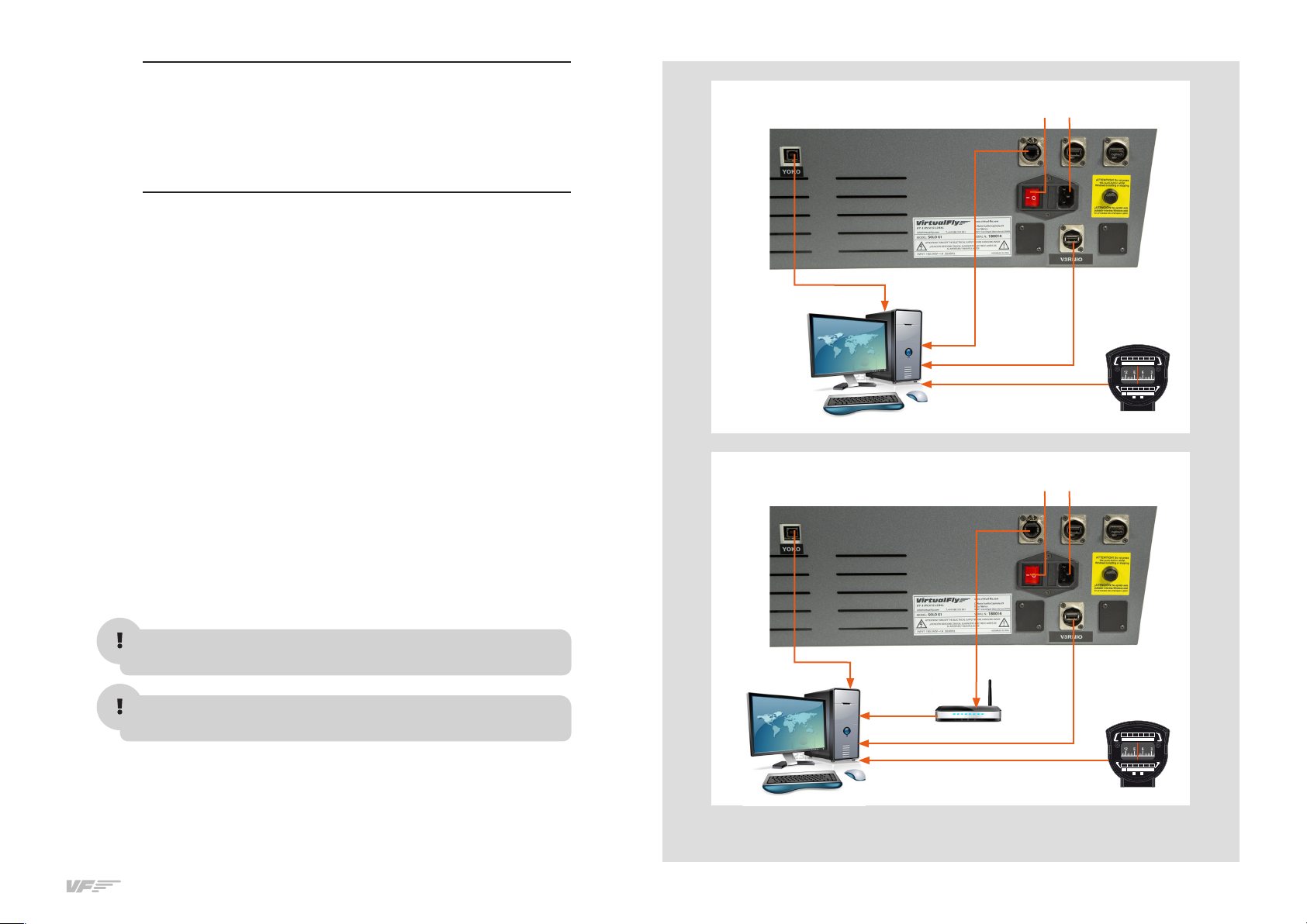
As "VF-Test&Calibrate-S” Control Panel communicates data from
YOKO, VRNIO and VF-COMPASS with MFS-PreparD, Keep in mind,
that VF-Test&Calibrate- S Control Panel has to remain ON when you
use MFS-PreparD.
.. VF-COMPASS, YOKO & VRNIO FLIGHT CONTROLS
CONFIGURATION
YOKO
YOKO calibration on Windows (example based on Windows 7)
• Go to control panel, “Devices and printers”.
If you see a YOKO+ instead of a YOKO, you can skip this step and
close the "Devices and printers" tab and go directly to "YOKO
Configuration Using VF-Test&Calibrate-S ".
• In the “Devices and printers”, right click on “VirtualFly - YOKO”.
• From the menu choose “Game controller settings”.
• In the Game controller window, double click on “VirtualFly - YOKO”
• Choose the “Settings” tab.
• Click on “Calibrate”.
• Once calibration is completed, go to the “Test” tab to check the correct
operation. Leaving the control in neutral position, the cross should be
centered in the box. Check the function of the six buttons as well.
• Click on “Apply”. Click “OK” to exit.
YOKO Configuration Using VF-Test&Calibrate-S
• Disable “Virtual-Fly YOKO” assignments on MFS/PD “Button and
keys” tab and “Axes” tab.
• Just duble click on the “VF-Test&Calibrate-S.exe” file to execute it.
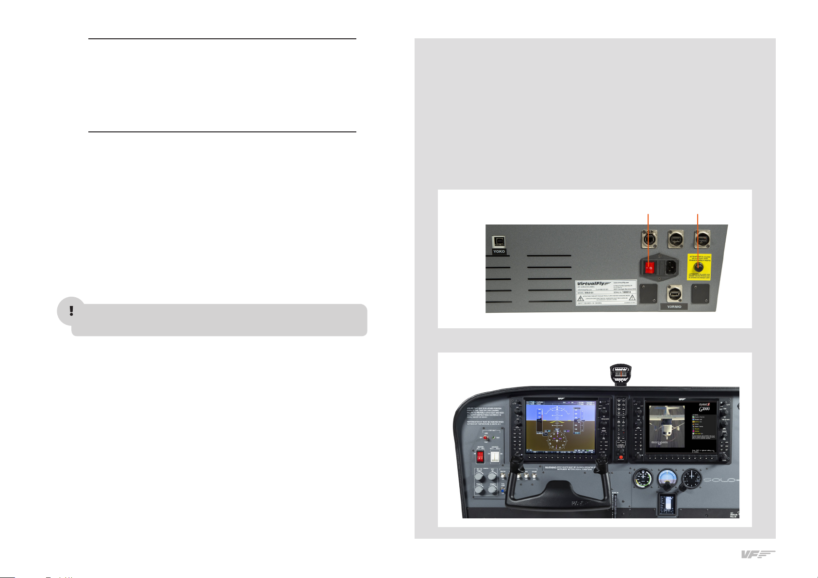
• To configurate the YOKO, you will find “VF-Test&Calibrate-S” user's gui-
de inside the Control Panel. See the arrow in the following figure.
• Click on "Save Current Configuration" button.

83. START UP THE SOLO-G1 - SOLO-G1 USER'S MANUAL
The SOLO-G incorporates a mini-computer that is to be connected to
the MFS/PD computer using the previously mentioned Network cable.
It is important to note that in no case should you access or manage
the SOLO-G1 mini-computer.
• On the MFS/PD computer activate the MFS/PreparD and load your
scenario with one of the planes installed from the memory stick.
• On the MFS/PD computer activate the “VFConnect.exe” and the
“VFTest&Calibrate-S.exe”.
ATTENTION DO NOT EXECUTE "VF-CONNECT.exe" before MFS/
PreparD is completely loaded.
• Activate the red switch on the back of the SOLO-G. (Figure 1)
• Press the black push-button on the back of the SOLO-G to acti-
vate the operating system. It is critical that never disconnect the
SOLO-G1 while charging programs. Doing so could cause starting
problems in the future.
• Wait about seconds until you see the message "Connected..." on
the “Client connection status” of the “VFConnect.exe” plugin in the
MFS/PD computer. You must see the STBY gauges and the Glass
Cockpit G are shown on SOLO-G. (Figure 2)
3. START UP
THE SOLO-G1
Switch ON Push
FIGURE
FIGURE
FOR
N3 06 0E 120 150
STEER
FOR
S2 10 240W 300330
STEER
ON NO
RADIO

9
3. START UP THE SOLO-G1 - SOLO-G1 USER'S MANUAL
•IfyouhavetheWindowsFireWallactivated,awarningpermissionto
communicate with networks appears, you must click "Allow Access".
•Oncetheconnection isestablished,youshouldsee animagelike
the second.
•Atthetop“ThisComputer”indicatesifthesoftwareMFS/P3disde-
tected. Only "Connected" will appear when you have initiated MFS/
Pd.
•At the bellow “Client Connection Status” indicates the connection
with the SOLO-G.
If you see the message "Searching..." on the “Client connection status”,
carefullyreadtheChapter7inthe"SOLO-G1_User'sManual"foundon
the memory stick.
DEACTIVATING THE SOLO-G
•Presstheblackpush-button(F)onthebackoftheSOLO-G1todeacti-
vatetheoperatingsystem.Waitfor"Windows"tocompletelystop.
•Once "Windows"isstopped,disconnect the red switch (2)onthe
back.
In this case
the pluggin is
searching the
MFS/Pd and
the SOLO-G
In this case
the pluggin is
connected to
MFS/Pd and
the SOLO-G
F

10 4. SELECTION OF PANEL TYPE - SOLO-G1 USER'S MANUAL
4. SELECTION
OF PANEL TYPE
(ACCORDING THE FSX/P3D PLANE)
The SOLO-G can represent panel types of general aviation aircraft,
Cessna CSP Skyhawk, Cessna Skylane II RG R and Cessna
T. The SOLO G panel will automatically display the corresponding
aircraft when you load it in the MFS-PD computer.
Remember that the SOLO G only works with the AIRCRAFT provided
in the memory stick.
FOR
N3 06 0E 120 150
STEER
FOR
S2 10 240W 3003 30
STEER
ON NO
RADIO
Indice
Altri manuali Aircatglobal Interruttore


