AirTech Air+ WALL Manuale di installazione e funzionamento
PLEASE READ INSTRUCTIONS IN CONJUNCTION WITH THE ILLUSTRATIONS.
PLEASE SAVE THESE INSTRUCTIONS
Positive Pressure System
Ventilation Unit
Air+ WALL
Installation & Commissioning Instructions
AIR+PIV/W
2
Installation and Wiring Instructions for the
Air+ Wall Positive Ventilation Unit.
INTRODUCTORY NOTES
The Unit is a positive input ventilation unit, designed to be installed on a wall of a
dwelling to continually supply filtered fresh air into the building. The system
consists of a fan unit with heater.
The Unit has an adjustable speed settings. These speeds are set during installation;
there are 4 pre-set speeds or an option allowing the speeds to be chosen manually from
10 L/s - 30 L/s. The Unit uses a sensor to monitor the supply temperature into the
room. If the ambient room temperature exceeds 27°C (adjustable during commissioning),
the unit will automatically switch to standby (no airflow), unless installed in radon
mode (selectable during commissioning).
All models are supplied with a heater; the element is activated by default when the
supply air temperature drops below the adjustable threshold. The heater will try and
maintain the supply air temperature at the threshold temperature. The threshold
temperature can be adjusted during commissioning.
The unit also incorporates a data logging function. This function will display total
runtime of system, energy consumption of the fan and energy consumption of the heater.
This data is resettable (when in data logging menu, hold the + and – button for 15
seconds until you see the word “RESET” on the display).
SAFETY AND GUIDANCE NOTES
IMPORTANT: READ THESE INSTRUCTIONS BEFORE
COMMENCING THE INSTALLATION
1.
DO NOT install this product in areas where the following may be
present or occur:
1.1.
Excessive oil or a grease laden atmosphere.
1.2.
Corrosive or flammable gases, liquids or vapours.
1.3.
Ambient temperatures higher than 40°C or less than -10°C.
1.4.
Possible obstructions which would hinder access or removal
of the Fan.
1.5.
Relative humidity above 90%
1.6.
Sudden ductwork bends or transformations close to the Unit.
1.7.
To achieve optimal airflow, the unit should be mounted 1.8m
from floor level.
2.
All wiring to be in accordance with the current I.E.E.
Regulations, or the appropriate standards of your country and MUST
be installed by a suitably qualified person.
3.
The fan must be provided with a 3A fused, isolator switch capable
of disconnecting all poles, having a contact separation of at
least 3mm.
4.
Ensure that the mains supply (voltage, frequency, and phase)
complies with the fan’s rating label.
5.
The fan should not be used where it is liable to be subjected to
direct water spray.
6.
This appliance can be used by children aged from 8 years and above
and persons with reduced physical, sensory or mental capabilities
or lack of experience and knowledge if they have been given
supervision or instruction concerning use of the appliance in a
3
safe way and understand the hazards involved. Children shall not
play with the appliance. Cleaning and user maintenance shall not
be made by children without supervision.
7.
Precautions must be taken to avoid the back-flow of gases into the
room from the open flue of gas or other fuel-burning appliances.
8.
Children of less than 3 years should be kept away unless
continuously supervised.
9.
Children aged from 3 to 8 years shall only switch on/off the
appliance provided the unit is installed as intended for normal
operation and they have been given supervision or instruction
concerning safe use of the appliance and understand the hazards
involved.
10.
Children aged 3 to 8 shall not plug in, regulate and clean the
appliance or perform user maintenance.
Caution - some parts of this product can become very hot and cause
burns. Particular attention has to be given where children and
vulnerable people are present.
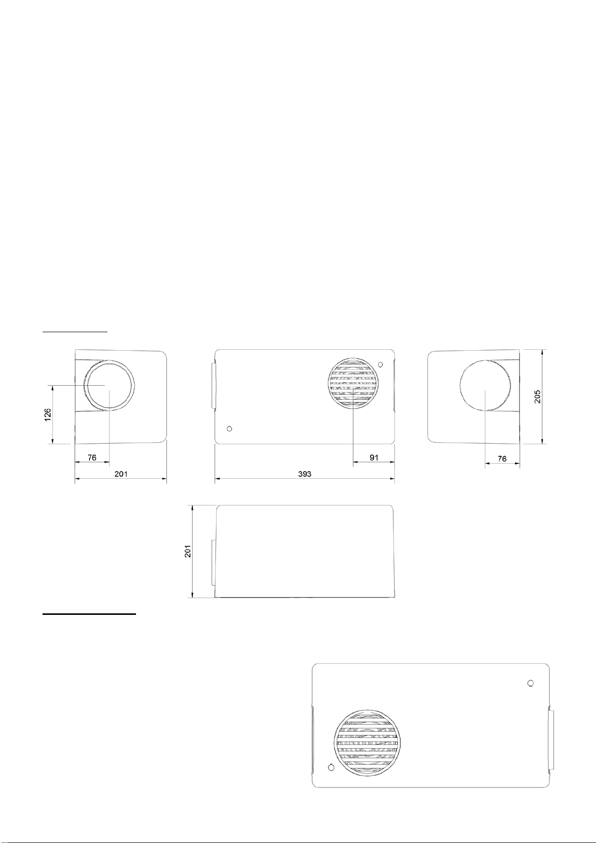
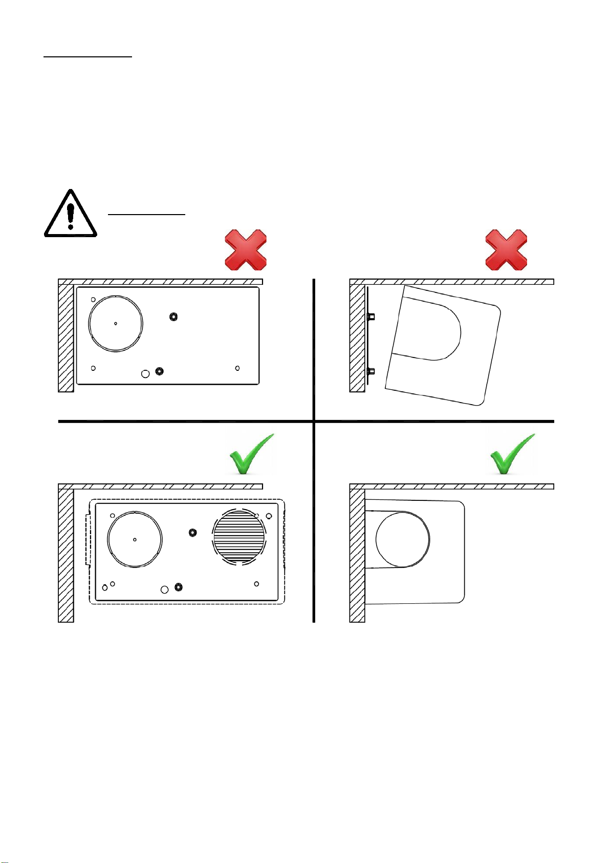
UNIT SIZE
UNIT MOUNTING
Unit to be mounted horizontally
To achieve optimal airflow, the unit should be mounted 1.8m from floor level.
If this is not possible, installation lower than 1.8m is safe and acceptable.
4
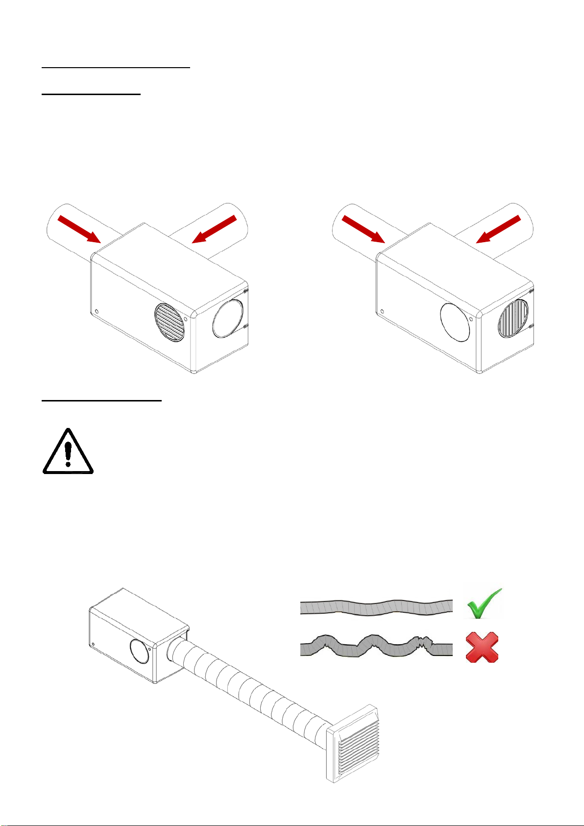
TYPICAL INSTALLATIONS
ABS COVER ONLY
See Inlet Options 1 or 2 for Install, page 8.
1. Insulate all ducting running from atmosphere and any ducting that passes through
an unheated space.
Choose either a side or rear inlet position for the unit.
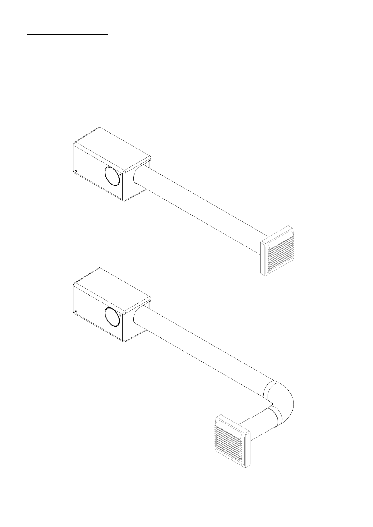
FLEX DUCT INSTALL
1. Securely connect the flexible ducting to the unit’s spigot, using worm-
drive clip or cable ties. See page 12, Outlet Option 3 for Install
details.
2. Extend the flexible ducting to its full length, to prevent moisture
collection & avoids airflow issues.
3. Secure diffuser to flexible ducting, using worm-drive clip or cable ties.
The total length of flexible duct in the system (Inlet and outlet) should
not exceed 2m. For the best performace and lowest noise, rigid ducting
should be used where possible.
The diagram below is simplified, the inlet ducts, duct cover and clips are not shown,
your installation may vary
5
RIGID DUCT INSTALL
1. Securely connect the rigid ducting to the unit’s spigot, using a suitable
adhesive. See Outlet Option 3 for Install, page 11.
2. Secure diffuser to the rigid ducting, using a suitable adhesive.
3. The total length of rigid duct in the system (Inlet and outlet) should
not exceed 2.5m, with a maximum of two 90° bends.
The diagrams below are simplified, the inlet ducts, duct cover and clips are not
shown, your installation may vary.
6
INSTALLATION
The Unit is wall-mounted using the bracket and fixings supplied (or other suitable
fasteners).
Ensure there is sufficient space around the unit’s base plate, when installing, to
allow fitting & removal of the cover for servicing & maintenance. (See image below).
The wall should have sufficient strength to support the unit.
Take into consideration the routing of the cable and the ducting that must be fitted
to the inlet spigot.
The unit can be mounted vertically or horizontally on a vertical wall.
IMPORTANT
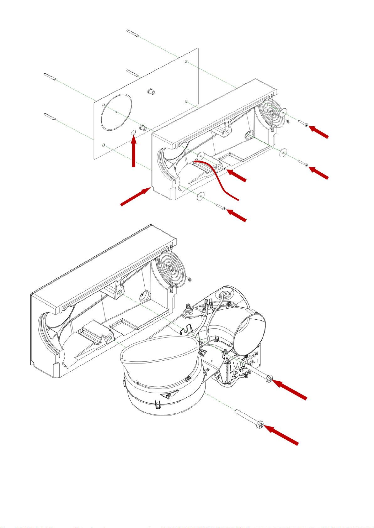
7
Hand tighten these 2
screws, when fitting the
scroll assembly.
Feed power supply (and
optional Heater Switch cable)
through Base plate or bottom
left hand side of unit, then
through the rear of the foam
before securing unit.
8
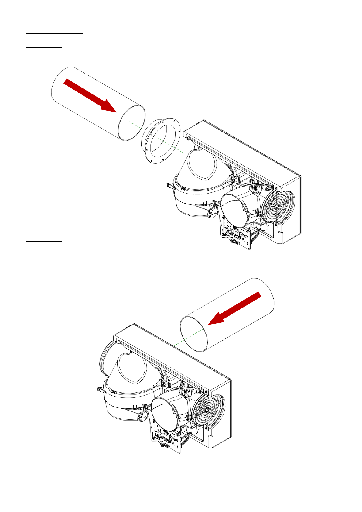
INLET OPTIONS
OPTION - 1
OPTION - 2
If installing the unit with the air supply
coming through the rear, the metal
plate cut-out will need to be removed from
base plate and the rear foam
case will need to be cut-out before mounting.
See next page for details.
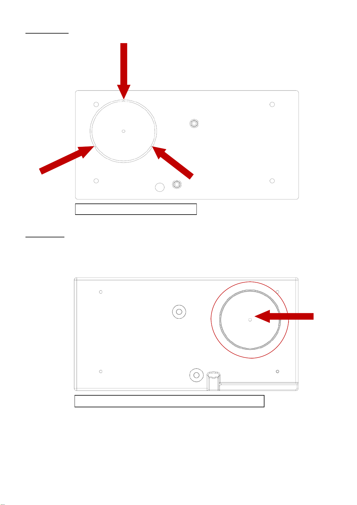
9
Base Plate
Rear Foam
Snip the three tabs to remove the insert
Using the centre mark, cut through the foam housing using a hole
10
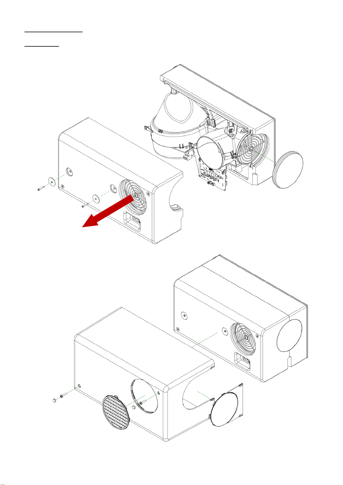
OUTLET OPTIONS
OPTION - 1
Questo manuale è adatto per i seguenti modelli
1
Indice
Altri manuali AirTech Fan


