
AMX AutoPatch CP-20A Manuale utente

Instruction Manual
AutoPatch Control Panel
CP-20A
Control Panel
Release: 2/29/2008

Contents
i
CP-20A Instruction Manual
Contents
Introduction.........................................................................................................1
Applicability Notice ................................................................................................................. 1
Overview ................................................................................................................................. 1
Executing Switches..............................................................................................4
Executing Switches – Selecting Input First .............................................................................. 4
Executing Switches – Selecting Output First ........................................................................... 6
Changing the Virtual Matrix .................................................................................................... 8
Disconnecting Switches .....................................................................................10
Disconnecting an Input..........................................................................................................10
Disconnecting an Output....................................................................................................... 12
Verifying Signal Status ......................................................................................14
Verifying Input Status............................................................................................................ 14
Verifying Output Status.........................................................................................................16
Executing Presets ..............................................................................................18
Global & Local Presets........................................................................................................... 18
Defining Global Presets.........................................................................................................19
Executing Global Presets....................................................................................................... 21
Adjusting Audio.................................................................................................23
Adjusting Output Volume...................................................................................................... 23
Adjusting Digital Input Gain .................................................................................................. 24
Adjusting LCD Contrast.....................................................................................27
Adjusting Contrast – Main Menu ........................................................................................... 27
Adjusting Contrast – Setup.................................................................................................... 27
Reloading Configuration File.............................................................................29
Checking Software Version ...............................................................................30
Checking Software – Setup ................................................................................................... 30
Installing a CP-20A Remote ...............................................................................31
Connecting to an AMX AutoPatch Router ............................................................................. 31
Applying Power ..................................................................................................................... 33
Rack Installation..................................................................................................................... 34
Linking Multiple Panels.......................................................................................................... 35
Completing the Installation ................................................................................................... 36
System Error Codes...........................................................................................38
Troubleshooting .................................................................................................................... 39
Technical Support.................................................................................................................. 39

Contents
ii CP-20A Instruction Manual
Introduction
1
CP-20A Instruction Manual
Introduction
Applicability Notice
The information in this manual applies to the CP-20A Control Panel, which comes with many of the
Modula pre-configured systems or can be ordered as a remote control panel or as part of a Modula or
Optima custom system.
Pre-Configured Systems
The CP-20A can be part of a pre-configured system made up of a Modula 3 RU or 4 RU. All Modula
pre-configured systems are numbered FGP34-xxxx-xxx (e.g., FGP34-1644-616).
Remote Control Panel
The CP-20A Remote Control Panel (Sales # FG1090-258) can be ordered as a separate unit to control an
Optima, Modula, or 8Y-3000 system.
Custom Systems
The CP-20A can be ordered as an option for Optima 3 RU, Modula 3 RU and 4 RU, and 8Y-3000 custom
systems.
Overview
The CP-20A is used for controlling the system’s switches and system attributes. Although control panels
are optional, we recommend one per system for system verification, redundant control, and
troubleshooting.
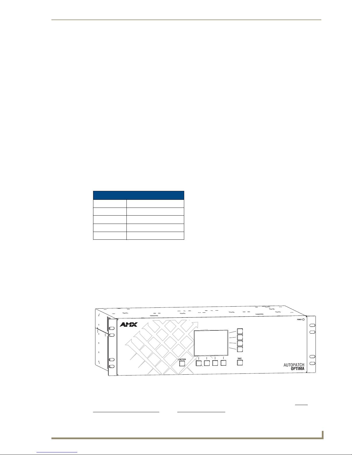
FIG. 1 illustrates an Optima Distribution Matrix with a CP-20A Control Panel. Other models may vary
slightly in appearance.
Note: AMX AutoPatch enclosures can also be controlled using BCS (Basic Control Structure)
commands transmitted through an external controller; for more information, see the BCS
Protocol Instruction Manual on the AMX AutoPatch CD or at www.amx.com.
Custom Systems
Enclosures Control Panel Sales #
8Y-3000 FG1043-216
Modula 3 RU FG1034-243
Modula 4 RU FG1034-246
Optima 3 RU FG1046-213
FIG. 1 CP-20A Control Panel on an Optima
Introduction
2CP-20A Instruction Manual
Keys & Functions
Graphic LCD
An LCD with a backlight displays instructions and selection entry fields. The backlight automatically
turns off after 15 minutes of inactivity. Press any key to reactivate the light.
Note: To adjust the contrast of the LCD, see “Adjusting LCD Contrast” on page 27.
Dynamic Menu Area
The menu displays different command options across the bottom of the LCD, depending on which
screen is active. These options can be accessed using the corresponding dynamic menu keys. The menu
options are multilevel with the ability to display custom input (source) and output (destination) names
(labels). The default channel name (e.g., O_Ch:0003 for Output 3) appears unless the name has been
modified in the configuration file* using XNConnect (for more information, see the XNConnect
Help file).
* The configuration file (.xcl file) contains routing and control information for a system and is modified
with XNConnect, which graphically displays the file. Both the configuration file and XNConnect are on
the AMX AutoPatch CD.
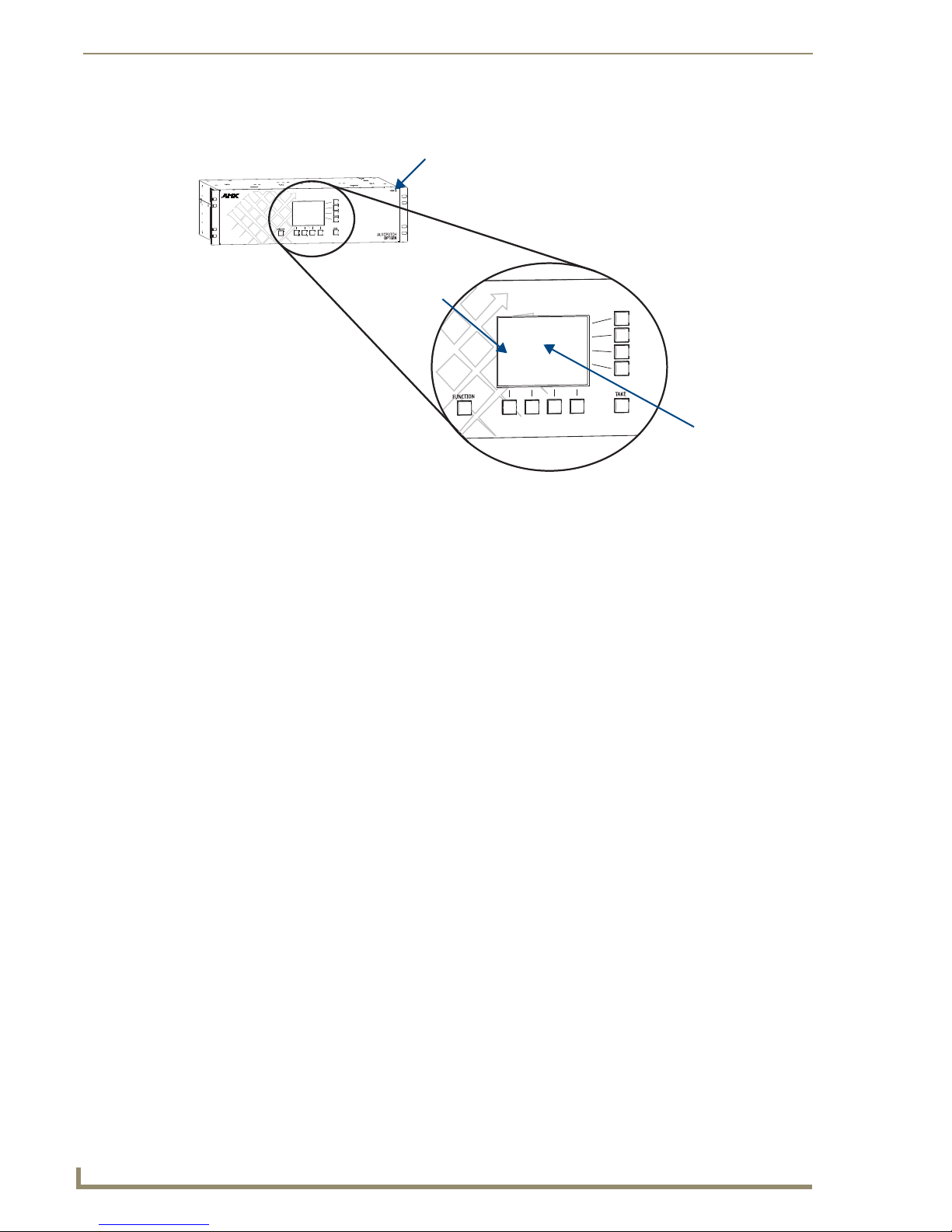
FIG. 2 Close-up view of a CP-20A Control Panel
Dynamic Menu Area
Power Indicator LED
Graphic LCD

Introduction
3
CP-20A Instruction Manual
Dynamic Menu Keys
The keys select commands and settings. Each menu key lines up with a different section of the dynamic
menu area. The four keys across the bottom select commands and settings which will vary according to
the screen displayed on the LCD.
The four keys on the right side of the LCD are used to scroll through lists, adjust sliders, select an action,
or return to the previous screen. The associated commands on the right side of the Dynamic Menu Area
vary by screen and include the following:
Back key – Use to return to the last screen. This key will not undo a completed operation.
Arrow keys – Use to scroll through lists and adjust sliders. When scrolling, press and hold an
arrow key to increase scrolling speed. When at the bottom of a list, press the down key to
access the top of the list. When at the top of a list, press the up key to access the bottom of the
list. Scrolling from the bottom of a list may sometimes be more efficient depending on the
matrix size.
Select key – Use to enter a selection. This key will not execute operations.
Function Key
The Function key accesses the Main Menu screen. From the Main Menu, the Function key accesses
additional menu options. From any other screen, it returns to the Main Menu.
Take Key
The Take key functions much like the Enter key on a computer keyboard. Pressing the Take key instructs
the system to execute a selected operation. Prior to pressing the Take key, the individual operation
component(s) must be selected by pressing the Select key.
CP-20A operations combine the following four basic tasks:
To choose a command – Press the dynamic menu key along the bottom that corresponds with
the command you want to choose.
To locate values for fields (such as virtual matrix, input, output, and preset values) – Press the
dynamic menu keys on the right that correspond to the arrows.
To enter a selection – Press the Select key. (The key that corresponds to the Select option on
the dynamic menu area is found on the right.)
To execute an operation – Press the Take key.
FIG. 3 Command & menu keys
Function Key Tak e Ke y
Select or Mute Key
Dynamic Command Keys
Navigation Keys
Back Key

Executing Switches
4CP-20A Instruction Manual
Executing Switches
A switch is an active connection between an input (source) device and one or more output (destination)
devices. The signals routed in a switching operation are individual signals or groups of individual signals
coming through the connectors on the rear of an enclosure. Executing a preset is a quick way to execute
multiple switches at a time. For information on presets, see page 18.
Switches are executed on the default virtual matrix unless otherwise specified. When specifying a virtual
matrix, be sure it includes all the signals you want to route. The number of the virtual matrix (VM) that
operations are currently being performed on is displayed in the upper-right of the display. If you need to
change the virtual matrix, see “Changing the Virtual Matrix” on page 8.
You can return to the Main Menu screen at any time by pressing the Function key.
Note: In each switch command, you can enter multiple output signals, but only one input signal.
However, you must select the input first in order to select multiple outputs. The Take key must be
pressed for the switch operation to execute.
Executing Switches – Selecting Input First
The example below routes Input 33: Satellite Dish to Output 6: Reception Monitor on
Virtual Matrix 0.
To execute a switch selecting Input first:
1. At the Main Menu screen, choose the Change command.
If the Change command is not available, press the Function key to view additional
Main Menu options.
The Change Input screen appears, displaying the available input options.

Executing Switches
5
CP-20A Instruction Manual
2. Locate Input 33: Satellite Dish by scrolling through the list using the arrow keys.
(Press and hold an arrow key to scroll quickly.)
3. Press the Select key.
The Change Output screen appears, displaying the available output options.
Note: If other outputs are already routed to the selected input, they are highlighted on the Change
Output screen.
4. Locate Output 6: Reception Monitor by scrolling through the list using the arrow keys.

Executing Switches
6CP-20A Instruction Manual
5. Press the Select key.
Output 6: Reception Monitor is highlighted.
Note: You can select multiple outputs by scrolling through the list and pressing the Select key. The
Select key functions as a toggle switch, selecting and unselecting outputs in the list each time it is
pressed. Any outputs that are already routed to the selected input are highlighted. Unselecting an
output(s) results in its disconnection when the Take key is pressed.
6. Press the Take key to execute the operation.
The switch from Input 33: Satellite Dish to Output 6: Reception Monitor occurs as soon
as the Take key is pressed.
The system returns to the Change Input screen.
7. Make additional switches.
Or
Press the Function key to return to the Main Menu screen.
Executing Switches – Selecting Output First
You can execute a switch by selecting one output first; however, to select multiple outputs you must use
the “Selecting Input First” method (see page 4).
The example below routes a signal to Output 15: Main Monitor Rm B from
Input 10: DVD #1 Control Rm on Virtual Matrix 0.
To execute a switch selecting output first:
1. At the Main Menu screen, choose the Change command.
If the Change command is not available, press the Function key to view additional
Main Menu options. The Change Input screen appears.

Executing Switches
7
CP-20A Instruction Manual
2. Choose the Output command from the bottom of the screen.
The Change Output screen appears, displaying the available output options.
3. Locate Output 15: Main Monitor Rm B by scrolling through the list using the arrow keys.
(Press and hold an arrow key to scroll quickly.)
4. Press the Select key.
The Change Input screen appears, displaying the available input options.
Note: If an input is already routed to the selected output, it is highlighted on the
Change Input screen.
Altri manuali per AutoPatch CP-20A
1
Indice
Altri manuali AMX Pannello di controllo

AMX
AMX Modero Viewpoint MVP-5200i Manuale utente

AMX
AMX AutoPatch CP-10 Manuale utente

AMX
AMX AutoPatch CP-20A Manuale utente

AMX
AMX AutoPatch CP-15 Manuale utente

AMX
AMX AutoPatch CP-15 Manuale utente

AMX
AMX Precis DSP Guida

AMX
AMX Novara CP2000 Series Manuale utente

AMX
AMX AutoPatch CP-10 Manuale utente

AMX
AMX Precis Manuale utente

AMX
AMX Modero X MXT-700 Manuale elenco delle parti


