Anolis ArcPad 48 Integral (SmartWhite) Manuale utente
Version 1.5

ArcPad 48 Integral (SmartWhite)
2
Table of contents
1. Safety instr ctions ...................................................................................................................................................... 3
2. Fixt re exterior view ................................................................................................................................................... 5
3. Installation .................................................................................................................................................................. 5
3.1 Mo nting the fixt re ............................................................................................................................................ 5
3.2 Connection to the mains ...................................................................................................................................... 6
3.3 Installation of the barn-doors ............................................................................................................................... 8
3.4 Setting and control ............................................................................................................................................... 9
3.5 DMX 512 connection .......................................................................................................................................... 10
3.6 Master/slave connection .................................................................................................................................... 10
3.7 Stand-alone operation ........................................................................................................................................ 10
4. ArcPad 48 Integral (SmartWhite) - DMX protocol .................................................................................................... 11
5. Control men map .................................................................................................................................................... 12
6. Fixt re men ............................................................................................................................................................. 14
6.1 Fixt re Address ................................................................................................................................................... 15
6.2 Fixt re information ............................................................................................................................................. 16
6.3 Personality .......................................................................................................................................................... 17
6.4 Man al mode ...................................................................................................................................................... 17
6. 5 Test seq ences................................................................................................................................................... 18
6.6 Stand-alone setting ............................................................................................................................................. 18
6.7 Special f nctions ................................................................................................................................................. 19
7. RDM .......................................................................................................................................................................... 21
8. Error and information messages .............................................................................................................................. 22
9. Technical specifications ............................................................................................................................................ 23
10. Cleaning and maintenance ..................................................................................................................................... 26

ArcPad 48 Integral (SmartWhite)
3
FOR YOUR OWN SAFETY, PLEASE READ THIS USER MANUAL CAREFULLY
BEFORE POWERING OR INSTALLING YOUR ArcPad 48 Inte ral !
Save it for future reference.
This device has left o r premises in absol tely perfect condition. In order to maintain this condition and to ens re a
safe operation, it is absol tely necessary for the ser to follow the safety instr ctions and warning notes written in
this man al.
The man fact rer will not accept liability for any res lting damages ca sed by the non-observance of this man al
or any na thorized modification to the device.
Please consider that damages ca sed by man al modifications to the device are not s bject to warranty.
1. Safety instructions
DANGEROUS VOLTAGE CONSTITUTING A RISK OF ELECTRIC SHOCK IS PRESENT WITHIN THIS UNIT!
Make s re that the available voltage is not higher than stated on the rear panel of the fixt re.
This fixt re sho ld be operated only from the type of power so rce indicated on the marking label. If yo are not
s re of the type of power s pplied, cons lt yo r a thorized distrib tor or local power company.
Always disconnect the fixt re from AC power before cleaning, removing or installing the f ses, or any part.
Do not overload wall o tlets and extension cords as this can res lt in fire or electric shock.
Make s re that the power/data cord is never crimped or damaged by sharp edges. Check the fixt re and the
power/data cord from time to time.
Do not install the nit near naked flames.
During the operation the housing becomes hot (up to 80°C)
Refer servicing to q alified service personnel.
This fixture falls under protection class I. Therefore this fixture has to be connected to a mains socket outlet with
a protective earthing connection.
Do not connect this fixt re to a dimmer pack.
LED li ht emission. Risk of eye injury.
Do not look strai ht at the fixture´s LEDs durin operation. The intense li ht beam may dama e your eyes.
Keep comp stible materials at least 20 cm away from the fixt re.
If the fixt re has been exposed to drastic temperat re fl ct ation (e.g. after transportation), do not switch it on
immediately. The arising condensation water might damage yo r device. Leave the device switched off ntil it has
reached room temperat re.
Avoid br te force when installing or operating the fixt re.
The fixt re was designed for o tdoor se. This fixt re m st not be sed for nderwater installation.

ArcPad 48 Integral (SmartWhite)
4
When choosing the installation spot, please make s re that the fixt re is not exposed to extreme heat or d st.
Avoid sing the nit in locations s bject to possible impacts.
The fixt re body never m st be covered with cloth or other materials.
Only operate the fixt re after having checked that the ho sing is firmly closed and all screws are tightly fastened.
Make s re that the area below the installation place is blocked when rigging, derigging or servicing the fixt re.
Do not block the front objective LEDs with any object when the fixt re is nder operation.
The fixt re becomes very hot d ring operation. Allow the fixt re to cool approximately 30 min tes prior to
manip late with it.
Operate the fixt re only after having familiarized with its f nctions. Do not permit operation by persons not
q alified for operating the fixt re. Most damages are the res lt of nprofessional operation!
Do not attempt to dismantle or modify the nit.
Please consider that na thorized modifications on the fixt re are forbidden d e to safety reasons!
Please se the original packaging if the fixt re is to be transported.
If this device will be operated in any way different to the one described in this man al, the prod ct may s ffer
damages and the g arantee becomes void. F rthermore, any other operation may lead to dangers like short-
circ it, b rns, electric shock etc.
ArcPad 48 Integral (SmartWhite)
5
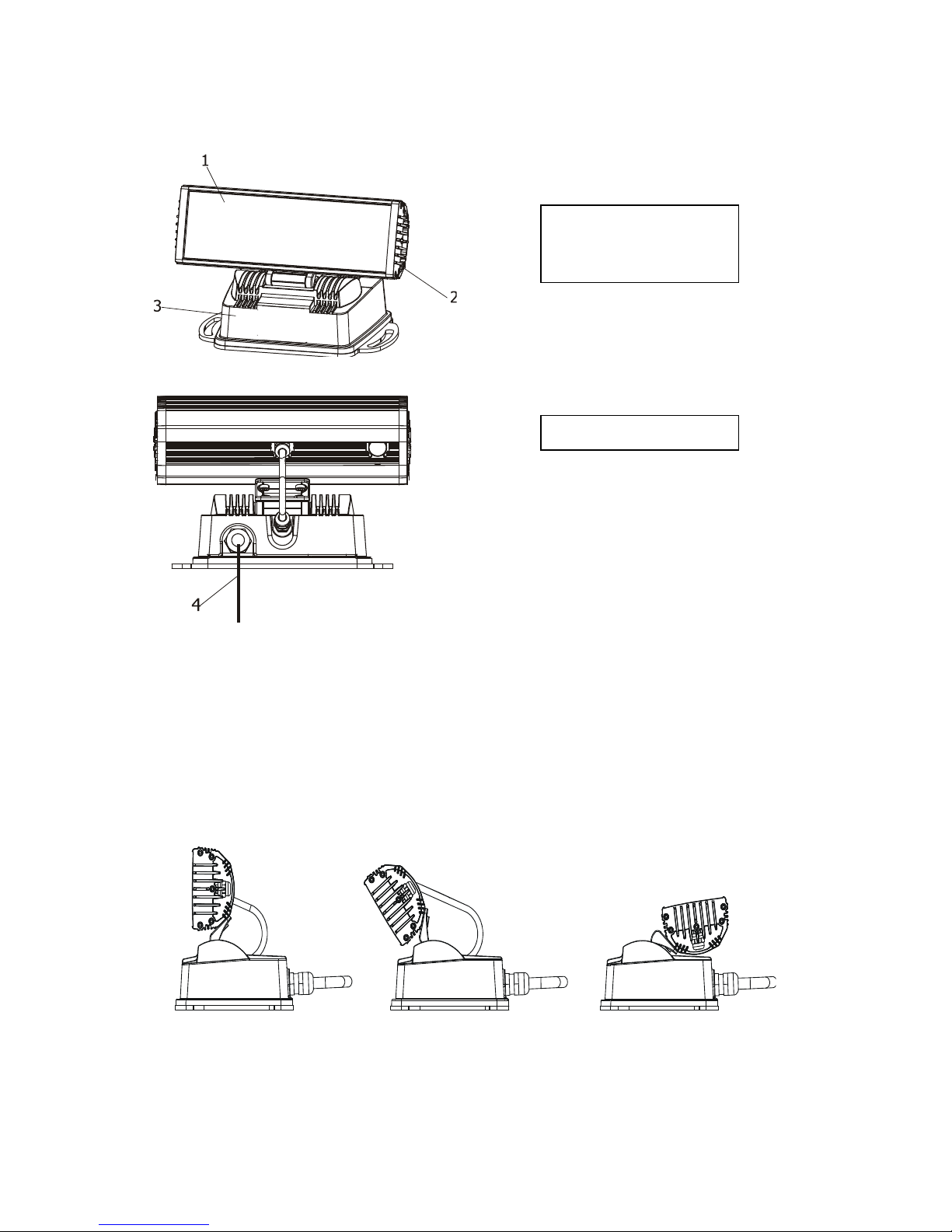
2. Fixture exterior view
3. Installation
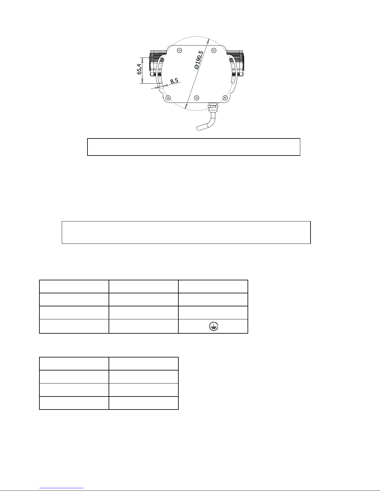
3.1 Mounting the fixture
The ArcPad 48 Integral can be arranged in any position orientation.The ArcPpad 48 Integral´s radiator with LEDs is
mo nted on an adj stable bracket for “tilt” adj stment into many positions:
Two slots (8.5mm wide) in the fixt re base serve for mo nting on the non-flammable flat s rface:
1. Lens array
2. Radiator
3.Base
6. Power/data cord
ArcPad 48 Integral (SmartWhite)
6
Ensure that the structure to which you are attachin
the fixture is secure
Caution: Overhead installation req ires experience. Fixt res may ca se severe inj ries when crashing down! If yo
have do bts concerning the safety of a possible installation, do not install the device and cons lt installation with
an expert.
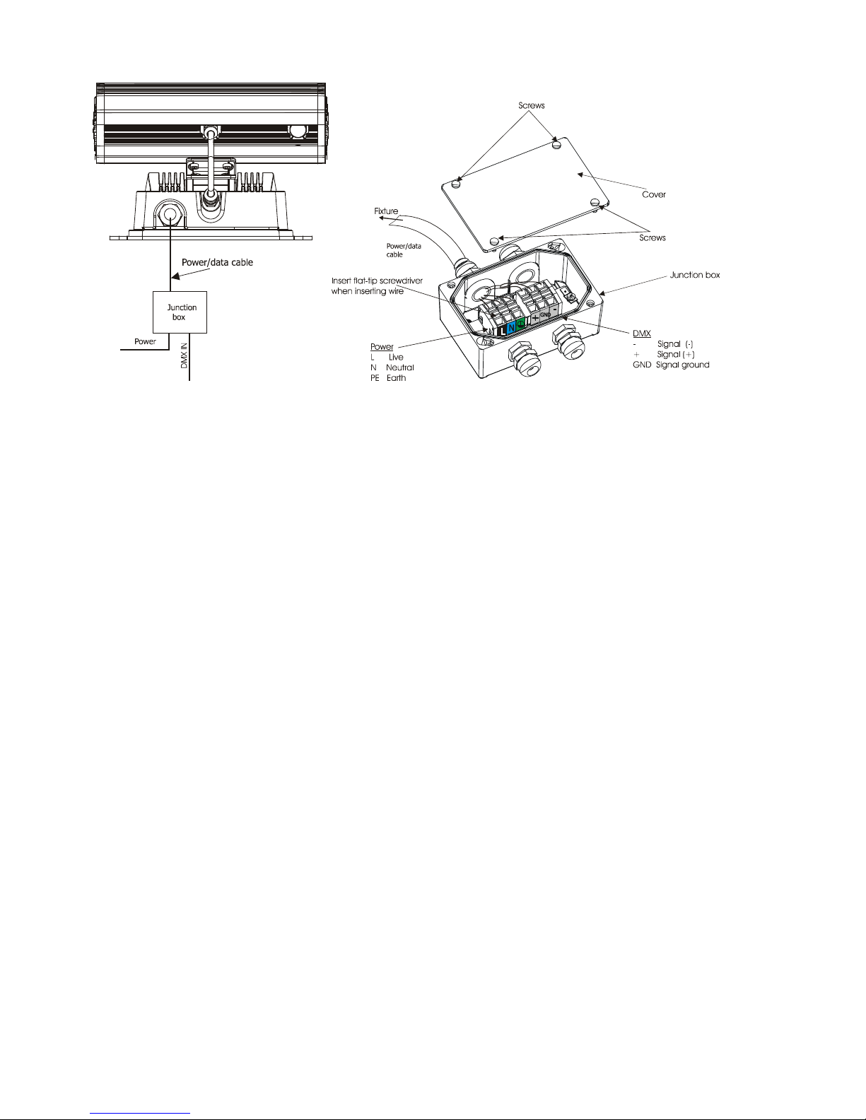
3.2 Connection to the mains
Fixtures must be installed by a qualified electrician in accordance with all national
and local electrical and construction codes and re ulation.
The ArcPad 48 Integral is eq iped with with a 5-cored power/data cable. The 3 cores serve for the power s pply
and next 2 shielded cores are intended for DMX connection.
The power cores are colo red according to the following table.
Core
Connection
Plug Terminal Marking
B
lack
Live
L
B
l e
Ne tral
N
Yellow/Green
Earth
This device falls under class one and must be grounded!
The data cores (DMX) are colo red according to the table:
Core
Connection
Brown
Data +
White
Data
-
Shielding
Data
gro nd
The power/data cable is connected to a j nction box as shown on the pict re below.
ArcPad 48 Integral (SmartWhite)
7
.
ArcPad 48 Integral (SmartWhite)
8
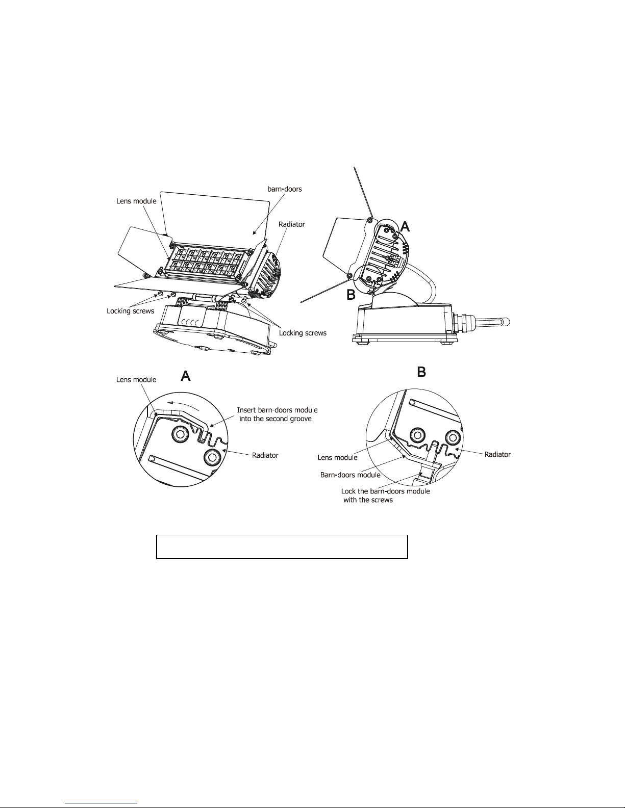
3.3 Installation of the barn doors
Yo can install the barn-doors to better define ill minated s rface.
To install the barn-door mod le:
1. Disconnect the fixt re from the mains.
2. P t the top edge of the barn-doors mod le into the second groove on the top side of the radiator ( detail
A) and the bottom edge into the second groove on the bottom side of the radiator and tighten fo r
locking screws M2 to sec re this barn-doors mod le on the radiator.
ever close the barn-doors during fixture operation
ArcPad 48 Integral (SmartWhite)
9
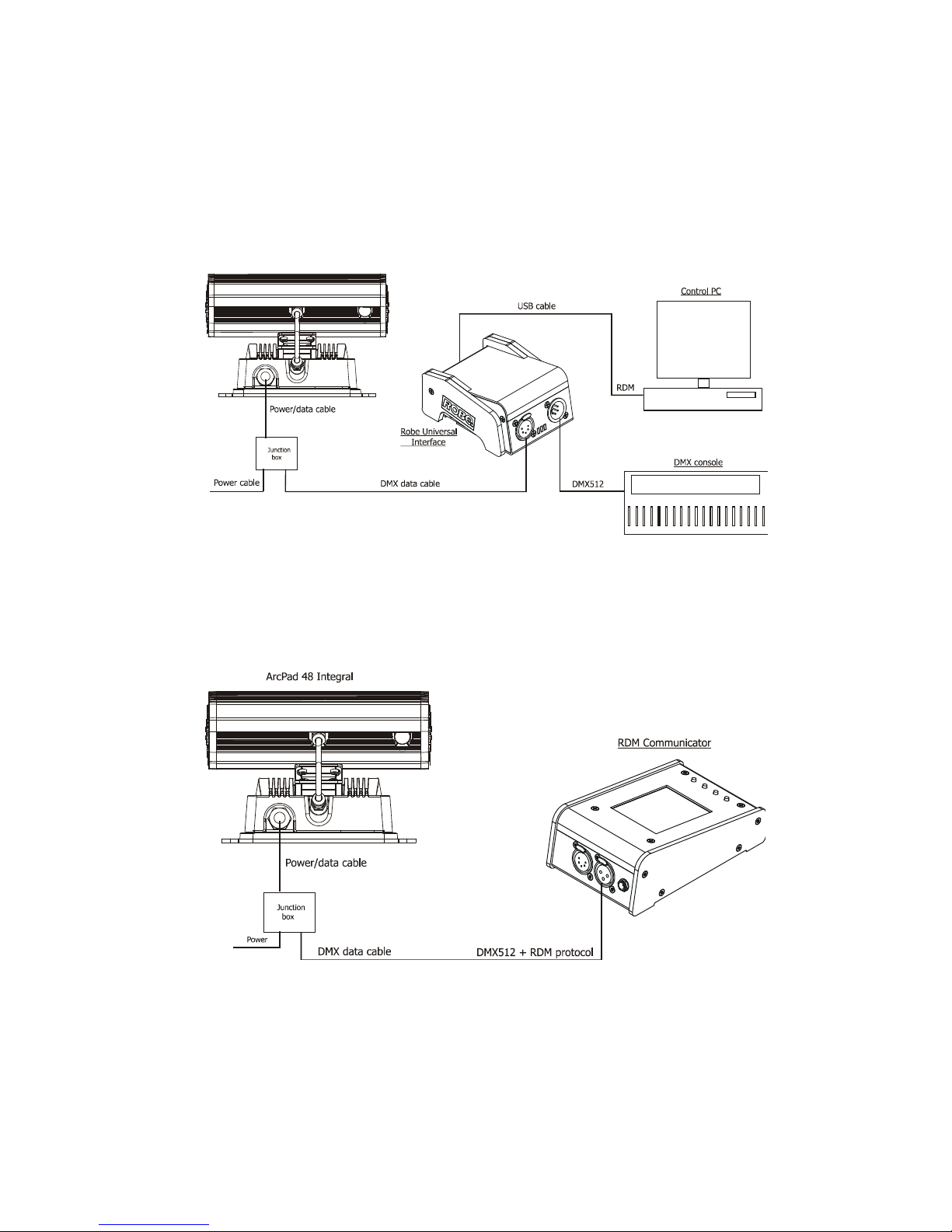
3.4 Setting and control
For setting DMX address, selecting DMX mode and for another settings yo need either Robe Universal Interface
or the RDM Comm nicator. Please see the Robe Universal Interface or RDM Comm nicator ser man als to get
more information abo t this prod cts. The way, how to connect these interfaces to the DMX data link is fig red
below.
OTE: never connect the RDM comm nicator and the The Robe Universal Interface to the fixt re at the same
time.
Robe Universal Interface
RDM Communicator
Note: DMX controller has to be disconnected from the fixt re when the RDM comm nicator is operated.

ArcPad 48 Integral (SmartWhite)
10
3.5 DMX 512 connection
To b ild a DMX chain
1. Connect the DMX o tp t of the controller directly with the DMX inp t of the first fixt re in the DMX chain.
2. Connect the DMX o tp t of the first fixt re in the DMX chain with the DMX inp t of the next fixt re.
3. Always connect the DMX o tp t with the inp t of the next fixt re ntil all fixt res are connected.
Do not overload the link. Max. 32 fixt res may be connected on a DMX link.
Ca tion: Terminate the o tp t of the last fixt re with a 120 Ohm resistor wired betwen data (+) and data (-) in
order to ens re the proper transmission on the data link.
3.6 Master/slave connection
To b ild a master/slave-chain:
Connect the DMX o tp t of the master fixt re in the data chain with the DMX inp t of the first slave. Always
connect o tp t with the inp t of the next slave ntil all slaves are connected ( p to 32 fixt res).
Ca tion: It is necessary to terminate the inp t of the master fixt re and the o tp t of the last slave with a 120 Ohm
resistor in order to ens re the proper transmission on the data link.
3.7 Stand alone operation
The fixt res on a data link are not connected to the controller b t can exec te pre-set programs which can be
different for every fixt re. To set the program to be played, see the "Stand-alone setting" (men "St.AL.").
"Stand-alone operation" can be applied to the single fixt re or to m ltiple fixt res operating synchrono sly.
Synchrono s operation of m ltiple fixt res req ires that they m st be connected on a data link and one of them is
set as a master (master mode) and the rest as the slaves (slave mode).
To set the fixt re as the master or slave, see the " Fixt re Address " (men "A001").
Only one fixt re can be set as the master.
The master fixt re starts sim ltaneo s program start in the other slave fixt res. All fixt res have a definite,
synchronized starting point when playing back their programs. The n mber of r nning program is the same in all
slaves and depends on the master's choice (men "St.AL.“). Every fixt re r ns its program repeatedly, starting the
program step No.1 when req ested by the master.
Example:
If the slave fixt re has a shorter program length, it will contin o sly repeat its program ntil the master fixt re
finishes its own program and restarts its program r nning (slave 1- prog.step 3 will not be finished).
If the slave fixt re has a longer program length, it will restart at prog. step 1 before it completes all its prog.steps
(slave 2 - prog.step 5 will not be played)- see the pict re bellow.
ote: Disconnect the fixt res from the DMX controller before master/slave operating, otherwise data collisions
can occ r and the fixt res will not work properly!
Indice
Altri manuali Anolis Proiettore


 Manuale utente")


