
Anolis ArcPad Xtreme (Single colour) Manuale utente
Version 1.
7

ArcPad Xtreme (Single colour)
2
Table of contents
1. Safety instructions ...................................................................................................................................................... 3
2. Fixture exterior iew ................................................................................................................................................... 4
3. Installation .................................................................................................................................................................. 5
3.1 Mounting the fixture ............................................................................................................................................ 5
3.2 Connection to the mains ...................................................................................................................................... 6
3.3 Installation of the barn-doors, top/half top hats ................................................................................................. 7
3.4 Setting and control ............................................................................................................................................... 7
3.5 DMX 512 connection ............................................................................................................................................ 8
3.6 Master/sla e connection ...................................................................................................................................... 8
3.7 Stand-alone operation .......................................................................................................................................... 9
4. ArcPad Xtreme (Single colour) - DMX protocol ........................................................................................................ 10
5. Control menu map .................................................................................................................................................... 11
6. Fixture menu ............................................................................................................................................................. 13
6.1 Fixture Address ................................................................................................................................................... 15
6.2 Fixture information ............................................................................................................................................. 15
6.3 Personality .......................................................................................................................................................... 16
6.4 Manual mode ...................................................................................................................................................... 16
6. 5 Test sequences................................................................................................................................................... 17
6.6 Stand-alone setting ............................................................................................................................................. 17
6.7 Special functions ................................................................................................................................................. 18
7. RDM .......................................................................................................................................................................... 20
8. Error and information messages .............................................................................................................................. 21
9. Technical specifications ............................................................................................................................................ 22
10. Cleaning and maintenance ..................................................................................................................................... 25
11.Apendix .................................................................................................................................................................... 26
11.1 ArcPad Xtreme EPS ........................................................................................................................................... 26
ArcPad Xtreme (Single colour)
3
FOR YOUR OWN SAFETY, PLEASE READ THIS USER MANUAL CAREFULLY
BEFORE POWERING OR INSTALLING YOUR ArcPad Xtreme !
Sa e it for future reference.
This de ice has left our premises in absolutely perfect condition. In order to maintain this condition and to ensure a
safe operation, it is absolutely necessary for the user to follow the safety instructions and warning notes written in
this manual.
The manufacturer will not accept liability for any resulting damages caused by the non-obser ance of this manual
or any unauthorized modification to the de ice.
Please consider that damages caused by manual modifications to the de ice are not subject to warranty.
1. Safety instructions
DANGEROUS VOLTAGE CONSTITUTING A RISK OF ELECTRIC SHOCK IS PRESENT WITHIN THIS UNIT!
Make sure that the a ailable oltage is not higher than stated on the rear panel of the fixture.
This fixture should be operated only from the type of power source indicated on the marking label. If you are not
sure of the type of power supplied, consult your authorized distributor or local power company.
Always disconnect the fixture from AC power before cleaning, remo ing or installing the fuses, or any part.
Do not o erload wall outlets and extension cords as this can result in fire or electric shock.
Make sure that the power/data cord is ne er crimped or damaged by sharp edges. Check the fixture and the
power/data cord from time to time.
Do not install the unit near naked flames.
During the operation the housing becomes hot (up to 85°C)
Refer ser icing to qualified ser ice personnel.
This fixture falls under protection class I. Therefore this fixture has to be connected to a mains socket outlet with
a protective earthing connection.
Do not connect this fixture to a dimmer pack.
LED light emission. Risk of eye injury.
Do not look straight at the fixture´s LEDs during operation. The intense light beam may damage your eyes.
Keep compustible materials at least 40 cm away from the fixture.
If the fixture has been exposed to drastic temperature fluctuation (e.g. after transportation), do not switch it on
immediately. The arising condensation water might damage your de ice. Lea e the de ice switched off until it has
reached room temperature.
Do not shake the fixture. A oid brute force when installing or operating the fixture.
The fixture was designed for indoor use and it is intended for professional application only. It is not for household
use.
ArcPad Xtreme (Single colour)
4
When choosing the installation spot, please make sure that the fixture is not exposed to extreme heat or dust.
A oid using the unit in locations subject to possible impacts.
The fixture body ne er must be co ered with cloth or other materials.
Only operate the fixture after ha ing checked that the housing is firmly closed and all screws are tightly fastened.
Make sure that the area below the installation place is blocked when rigging, derigging or ser icing the fixture.
Do not block the front objecti e LEDs with any object when the fixture is under operation.
The fixture becomes ery hot during operation. Allow the fixture to cool approximately 40 minutes prior to
manipulate with it.
Operate the fixture only after ha ing familiarized with its functions. Do not permit operation by persons not
qualified for operating the fixture. Most damages are the result of unprofessional operation!
Do not attempt to dismantle or modify the unit.
Please consider that unauthorized modifications on the fixture are forbidden due to safety reasons!
Please use the original packaging if the fixture is to be transported.
If this de ice will be operated in any way different to the one described in this manual, the product may suffer
damages and the guarantee becomes oid. Furthermore, any other operation may lead to dangers like short-
circuit, burns, electric shock etc.
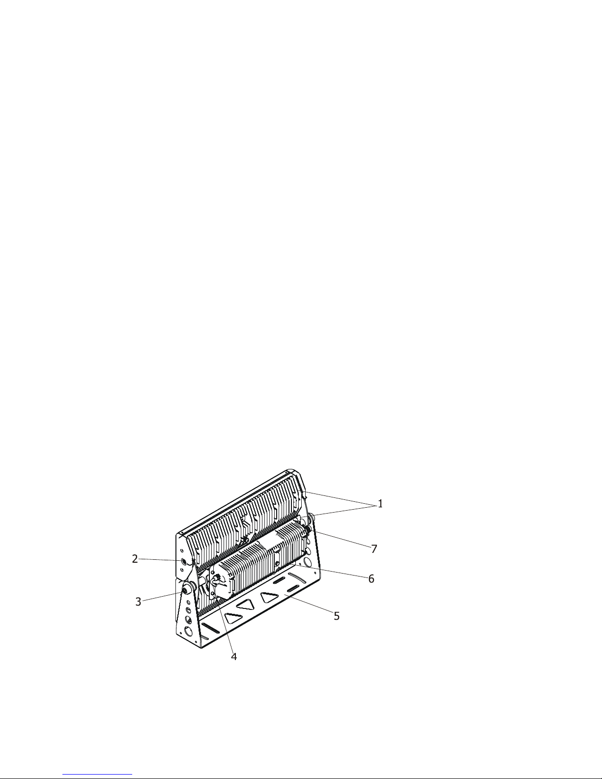
2. Fixture exterior view
1. LED modules
5. Mounting bracket
2. Tilt-locks for LED modules 6. Control unit
3 Tilt-lock for both LED modules 7. LED modules supply
4. Power/data cable
ArcPad Xtreme (Single colour)
5
3. Installation
3.1 Mounting the fixture
Ensure that the structure (truss, wall) to which you are attaching
the fixture is secure.
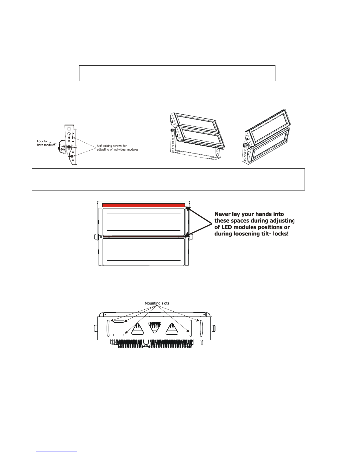
The ArcPad Xtreme can be arranged in any position orientation. The ArcPad Extreme allows to adjust its LED
modules to the desired position either both modules together (by means of the Allen key 14 ) or each module
separately (by means of the self-locking screws).
Danger of injury! Two workers ha e to handle with the fixture including adjusting the LED modules to
the desired position. The LED modules are ery hea y.
Fi e slots in the mounting bracket ser e for mounting the fixture on non-flammable flat surface.
Caution: O erhead installation requires experience. Fixtures may cause se ere injuries when crashing down! If you
ha e doubts concerning the safety of a possible installation, do not install the de ice and consult installation with
an expert.
ArcPad Xtreme (Single colour)
6
3.2 Connection to the mains
Fixtures must be installed by a qualified electrician in accordance with all national
and local electrical and construction codes and regulation
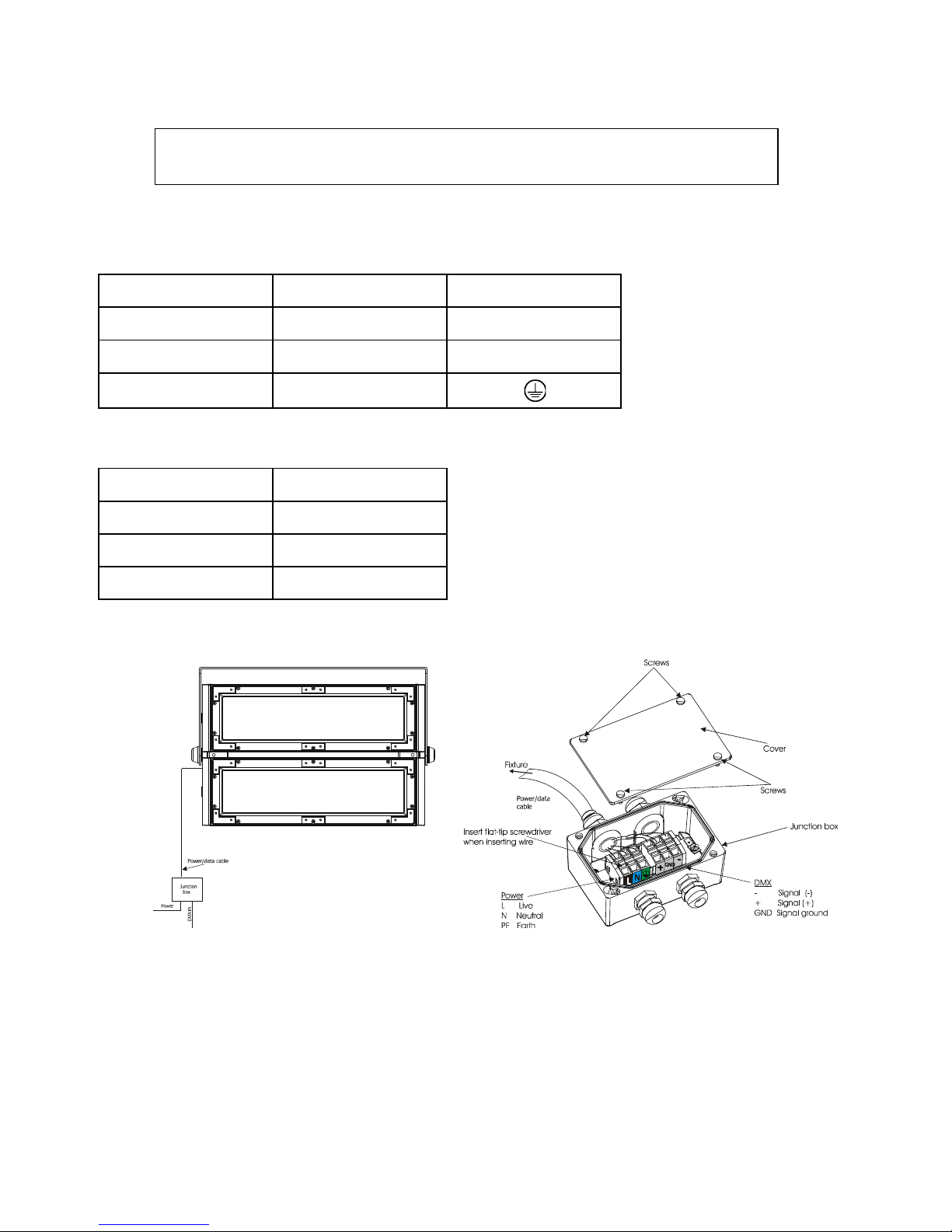
The ArcPad Xtreme is equiped with a 5-cored power/data cable. The 3 cores ser e for the power supply and next
2 shielded cores are intended for DMX connection.
The power cores are coloured according to the following table.
Core
Connection
Plug Terminal Marking
Black
Li e
L
B
lue
Neutral
N
Yellow/Green
Earth
This device falls under class one and must be grounded!
The data cores (DMX) are coloured according to the table:
Core
Connection
Red
Data +
White
Data
-
Shielding
Data
ground
The power/data cable is connected to a junction box as shown on the picture below.
ArcPad Xtreme (Single colour)
7
3.3 Installation of the barn doors, top/half top hats
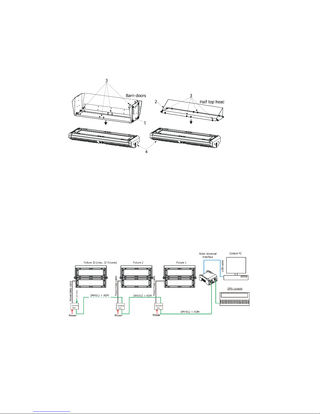
You can install barn-doors or top hats to better define illuminated surface.
Before installing the equipment disconnect the fixture from the mains.
1. Fit the barn-doors module (1) or top/half top hat (2) on the LED module (4) and fasten it by means of the
12 screws (3) as shown on the picture below.
2. Repeat the same steps for the second LED module of the fixture.
ever close the barn-doors during fixture operation!
3.4 Setting and control
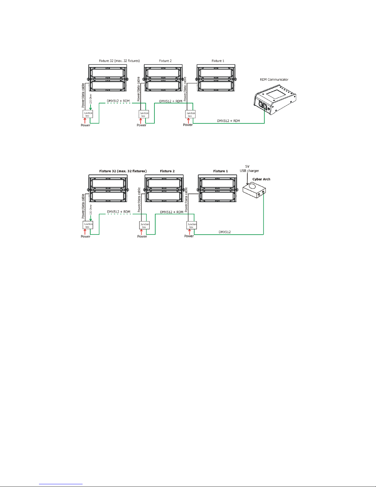
For setting DMX address, selecting DMX mode and for another settings you need either Robe Uni ersal Interface
or the RDM Communicator. Please see the Robe Uni ersal Interface or RDM Communicator user manuals to get
more information about this products. The way, how to connect these interfaces to the DMX data link is figured
below.
OTE: ne er connect the RDM communicator and the The Robe Uni ersal Interface to the fixture at the same
time.
1.Robe Universal Interface
ArcPad Xtreme (Single colour)
8
2. RDM Communicator
Note: DMX controller has to be disconnected from the fixture when the RDM communicator is operated.
After addressing and setting fixtures´beha iour you can use the Cyber Arch (after programming it) for stand-alone
operation of fixtures.
3.5 DMX 512 connection
To build a DMX chain
1. Connect the DMX output of the controller directly with the DMX input of the first fixture in the DMX chain.
2. Connect the DMX output of the first fixture in the DMX chain with the DMX input of the next fixture.
3. Always connect the DMX output with the input of the next fixture until all fixtures are connected.
Do not o erload the link. Max. 32 fixtures may be connected on a DMX link.
Caution: Terminate the output of the last fixture with a 120 Ohm resistor wired betwen data (+) and data (-) in
order to ensure the proper transmission on the data link.
3.6 Master/slave connection
To build a master/sla e-chain:
Connect the DMX output of the master fixture in the data chain with the DMX input of the first sla e. Always
connect output with the input of the next sla e until all sla es are connected (up to 32 fixtures).
Caution: It is necessary to terminate the input of the master fixture and the output of the last sla e with a 120 Ohm
resistor in order to ensure the proper transmission on the data link.
ArcPad Xtreme (Single colour)
9
3.7 Stand alone operation
The fixtures on a data link are not connected to the controller but can execute pre-set programs which can be
different for e ery fixture. To set the program to be played, see the "Stand-alone setting" (menu "St.AL.").
"Stand-alone operation" can be applied to the single fixture or to multiple fixtures operating synchronously.
Synchronous operation of multiple fixtures requires that they must be connected on a data link and one of them is
set as a master (master mode) and the rest as the sla es (sla e mode).
To set the fixture as the master or sla e, see the " Fixture Address " (menu "A001").
Only one fixture can be set as the master.
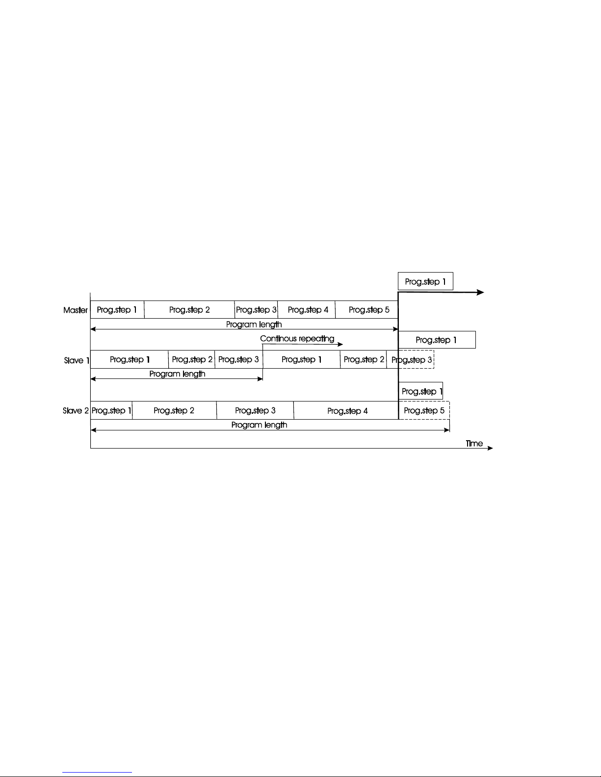
The master fixture starts simultaneous program start in the other sla e fixtures. All fixtures ha e a definite,
synchronized starting point when playing back their programs. The number of running program is the same in all
sla es and depends on the master's choice (menu "St.AL.“). E ery fixture runs its program repeatedly, starting the
program step No.1 when requested by the master.
Example:
If the sla e fixture has a shorter program length, it will continuously repeat its program until the master fixture
finishes its own program and restarts its program running (sla e 1- prog.step 3 will not be finished).
If the sla e fixture has a longer program length, it will restart at prog. step 1 before it completes all its prog.steps
(sla e 2 - prog.step 5 will not be played)- see the picture bellow.
ote: Disconnect the fixtures from the DMX controller before master/sla e operating, otherwise data collisions
can occur and the fixtures will not work properly!
ArcPad Xtreme (Single colour)
10
4. ArcPad Xtreme (Single colour) DMX protocol
Version 1.0
Mode
Value Function Type of control
1
2
3
4
- - 1 1 0 - 255
Dimmer
–
LED module 1
Dimmer intensity from 0% to 100%
proportional
- - 2 2 0 - 255
Dimmer
–
LED module 2
Dimmer intensity from 0% to 100%
proportional
-
1
-
3
0-31
32-63
64-95
96-127
128-143
144-159
160-191
192-223
224-255
Strobe
–
both LED modules
Shutter closed
Shutter open
Strobe-effect from slow to fast
Shutter open
Opening pulses in sequences slow--> fast
Closing pulses in sequences fast --> slow
Shutter open
Random strobe-effects from slow to fast
Shutter open
step
step
proportional
step
proportional
proportional
step
proportional
step
1
2
-
4
0 - 255
Dimmer
–
both LED modules
Dimmer intensity from 0% to 100%
proportional
-
3
-
5
0 - 255
Dimmer fine
–
both LED modules
Fine dimmer intensity from low to high
proportional
Questo manuale è adatto per i seguenti modelli
3
Indice
Altri manuali Anolis Proiettore


