AP TC5-1V10SA Manuale utente
TC5-1V10SA
Environment Control
USER'S MANUAL
M 890-00167 rev. 06 REV. 01

2TC5-1V10SA rev.06
TABLE OF CONTENTS
PRECAUTIONS .............................................................. 3
FEATURES..................................................................... 4
LOCATION OF THE CONTROLS................................... 6
ControllerStatusLeds................................................... 7
InternalSwitches ........................................................... 7
INSTALLATION .............................................................. 8
MountingInstructions ..................................................... 8
Connections.................................................................. 8
MotorTypes.................................................................. 9
Heating/CoolingOption................................................. 10
TemperatureProbes .....................................................10
CHANGING THE PARAMETER SETTINGS .................. 13
UsingtheDisplay .......................................................... 13
LockingtheParametersSettings ..................................14
TEMPERATURE SETTINGS .......................................... 15
TemperatureUnits.........................................................15
ViewingTemperatures ..................................................15
TemperatureSetPoint ..................................................18
TemperatureCurve .......................................................19
VENTILATION SETTINGS.............................................. 23
CoolingOperation......................................................... 23
MinimumVentilationCycle ............................................26
HumidityCompensation ................................................28
MinimumSpeedCurve.................................................. 31
DifferentialSettings....................................................... 37
Mist Cooling..................................................................39
HEATER SETTINGS....................................................... 42
ALARM SETTINGS......................................................... 47
TEST MODE.................................................................... 48
TROUBLESHOOTING GUIDE........................................ 49
TECHNICAL SPECIFICATIONS..................................... 53
FACTORY SETTINGS .................................................... 54
GLOSSARY..................................................................... 57
Page

3
TC5-1V10SArev.06
We strongly recommend installing supplementary natural
ventilation as well as a back-up thermostat on at least one
cooling stage (refer to the wiring diagram enclosed with this
user's manual to connect the thermostat).
Although fuses at the input and outputs of the controller
protect its circuits in case of an overload or overvoltage, we
recommend installing an additional protection device on the
controller's supply circuit.
The room temperature where the controller is located MUST
ALWAYS REMAIN BETWEEN 32°F AND 104°F (0°C TO 40°C).
To avoid exposing the controller to harmful gases or exces-
sive humidity, it is preferable to install it in a corridor.
DO NOT SPRAY WATER ON THE CONTROLLER
PRECAUTIONS
FOR CUSTOMER USE
Entertheserialnumberlocatedonthe
sideofthecontroller below forfuture
reference.
Modelnumber:
Serialnumber: TC5-1V10SA

4TC5-1V10SA rev.06
The TC5-1V10SA is an electronic device used for environmental control in
livestock buildings. It allows the user to maintain a specified target tem-
perature by controlling the operation of ventilation and heating equipment.
One stage of variable speed fans can be connected to the controller, as
well as eight stages of constant-speed fans and two stages of either con-
stant-speed fans or heating units. In addition, one of the constant-speed
fan stages can be configured as a mist cooling stage.
The main features of the TC5-1V10SA are as follows:
THREE-DIGITDISPLAY
A three-digit display provides a high level of accuracy, allowing the user to
specify a temperature to within one tenth of a degree (in Fahrenheit or
Celsius units).
PILOT LIGHTS
Pilot lights indicating the state of outputs allow the user to monitor the
operation of the system without having to enter the building.
MINIMUMVENTILATION CYCLE
When ventilation is not required for cooling, the first stage fans can be
operated either continuously or intermittently to reduce the level of humid-
ity and supply oxygen to the room.
TEMPERATURE AND MINIMUM VENTILATION SPEED CURVES
Thecontrollercanbeset to automaticallychangethetemperatureset point
and the minimum ventilation speed over a given period of time in accor-
dance with the user's requirements by specifying a temperature curve and
a minimum ventilation speed curve with up to six different points each.
CHOICE OF TEN MOTOR CURVES
Thevariationinmotorspeed resulting from achangeinvoltagewill depend
on the make and capacity of the motor. In order to achieve a high degree
of compatibility between controller and motor, the user can choose from
among ten different motor curves, thus ensuring that the correct voltage is
supplied.
ZONED OR CASCADING HEATERS
FEATURES

5
TC5-1V10SArev.06
TC5-1V10SA
HIGH/LOW TEMPERATUREALARM OUTPUT
HUMIDITYCOMPENSATION
Thestage1minimumspeed can be adjustedautomaticallyasafunction of
relative humidity. As humidity increases, the minimum speed of stage 1
fansincreasesproportionnallytocompensatefor the change.
FULL-SPEED FAN START-UP
In order to overcome the inertia of the ventilation system components and
de-ice the fan blades in cold weather conditions, the controller supplies
maximumvoltagetothevariable speed fansduringthe2seconds immedi-
ately following each start-up.
FOURINDEPENDENT TEMPERATURE PROBE INPUTS
Uptofour temperature probescanbe connected tothecontroller in orderto
obtain a more accurate reading of the average ambient temperature and a
faster reaction time.
OVERLOADAND OVERVOLTAGEPROTECTION
Fuses are installed at the input and outputs of the controller to protect its
circuitryinthecaseof an overload orovervoltage.
COMPUTERCONTROL
The controller can be connected to a computer, thus making it possible to
centralizethemanagementofinformation and diversify controlstrategies.
CONTROL OF AIR INLET MOVEMENT
IftheTC5-1V10SA is usedincombinationwith a PF-6controller, the move-
mentoftheair inletscanbecoordinated with theoperationof the fansusing
a potentiometer located on the panel drive. This allows the air inlets to be
adjusted correctly, without the influence of uncontrollable factors such as
windorairfromadjoining rooms.
TEST MODE
Atestmodeallows you to simulatetemperaturechangesand verify control-
lerperformance.
6TC5-1V10SA rev.06
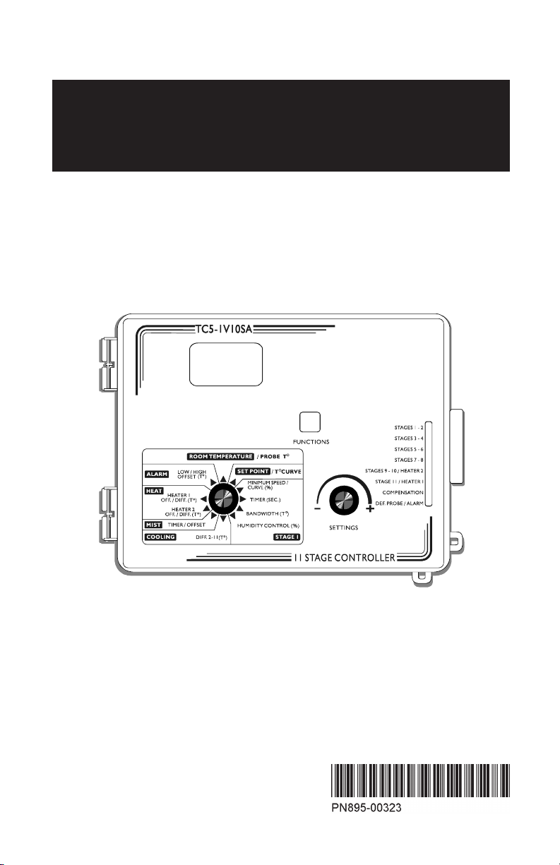
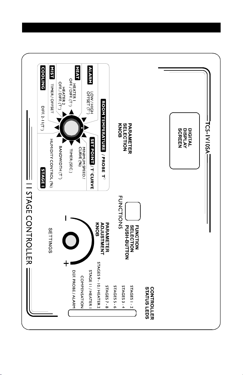
LOCATION OF THE CONTROLS
7
TC5-1V10SArev.06
TC5-1V10SA
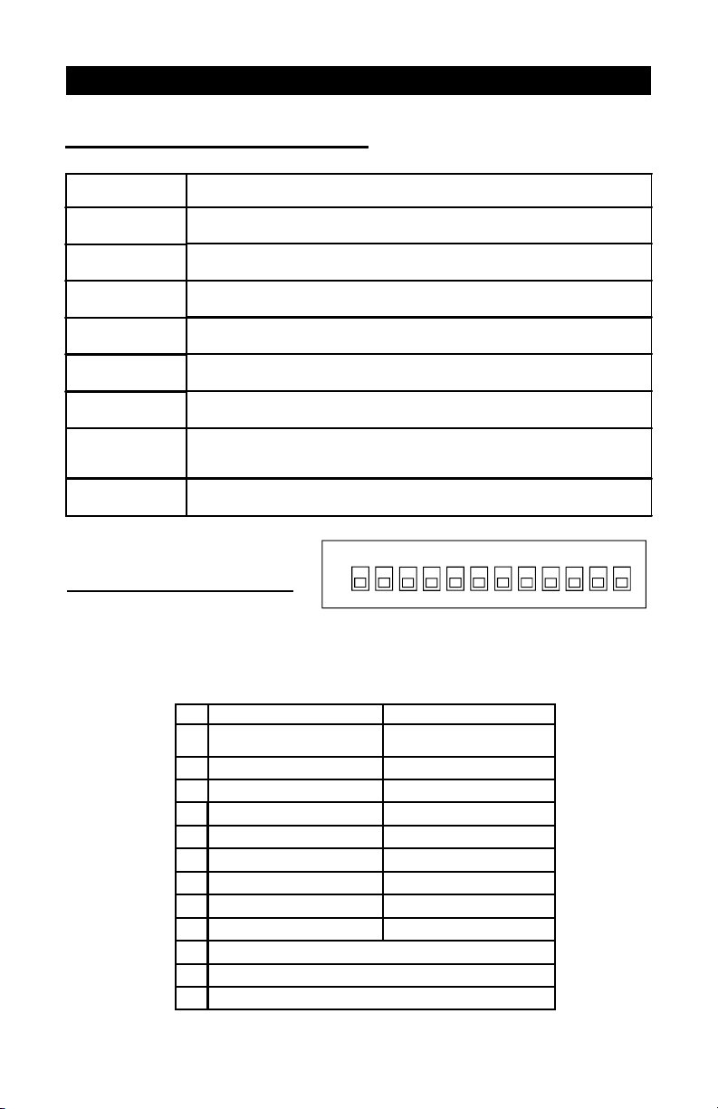
LED MEANING
STAGES 1-2 FLASHES WHEN STAGE 1 FANS ARE ON AND STAYS ON WHEN
STAGE 2 FANS ARE ON.
STAGES 3-4 FLASHES WHEN STAGE 3 FANS ARE ON AND STAYS ON WHEN
STAGE 4 FANS ARE ON.
STAGES 5-6 FLASHES WHEN STAGE 5 FANS ARE ON AND STAYS ON WHEN
STAGE 6 FANS ARE ON.
STAGES 7-8 FLASHES WHEN STAGE 7 FANS ARE ON AND STAYS ON WHEN
STAGE 8 FANS ARE ON.
STAGES 9-10 /
HEATER 2 FLASHES WHEN STAGE 9 FANS ARE ON AND STAYS ON WHEN
STAGE 10 FANS OR HEATING UNITS ARE ON.
STAGE 11 /
HEATER 1 TURNS ON WHEN STAGE 11 FANS OR HEATING UNITS ARE ON.
COMPENSATION TURNS ON WHEN THE COMPENSATION ON STAGE 1 MINIMUM
VENTILATION SPEED IS IN EFFECT OR WHEN THE COMPENSATION
ON THE MIST STAGE IS IN EFFECT.
DEF. PROBE/
ALARM TURNS ON WHEN AN ALARM IS DETECTED. BLINKS WHEN A
DEFECTIVE PROBE IS DETECTED.
CONTROLLER STATUS LEDS
#OFF ON
1UNLOCKED
PARAMETERS LOCKED PARAMETERS
2FAHRENHEIT DEGREES CELSIUS DEGREES
3PROBE 2 DISABLED PROBE 2 ENABLED
4PROBE 3 DISABLED PROBE 3 ENABLED
5PROBE 4 DISABLED PROBE 4 ENABLED
6NO HEATING HEATING
71 HEATER 2 HEATERS
8CASCADING HEATERS ZONED HEATERS
9MIST OFF MIST ON
10 RESERVED
11 RESERVED
12 RESERVED
INTERNAL SWITCHES
The internal switches are located on the inside of the front cover.
When the controller is shipped from the factory, all the switches are
set to OFF.
ON
2
134 6 75 8 9 11
10 12

8TC5-1V10SA rev.06
Toconnectthecontroller,refertothewiringdiagramenclosedwiththisuser's
manual.
nSet the voltage switch to the appropriate voltage.
nUse the electrical knockouts provided at the bottom of the enclosure.
Donotmakeadditionalholes intheenclosure, particularlyontheside
oftheenclosurewhen using acomputercommunicationsmodule.
nIf Stage 10 or 11 is used for heating, it may be necessary to install a
transformerinordertosupplytheappropriatevoltagetotheheatingunit.
ALARMCONNECTION: Therearetwotypesofalarmsonthemarket. One
typeactivateswhencurrentiscutoffatitsinput,whereastheotheractivates
whencurrentissuppliedatitsinput. Foranalarmofthefirsttype,usetheNO
terminalasshownonthewiringdiagram. Foranalarmofthesecondtype,use
theNCterminal.
ALL WIRING MUST BE DONE BY AN AUTHORIZED ELECTRI-
CIAN AND MUST COMPLY WITH APPLICABLE CODES, LAWS
AND REGULATIONS. BE SURE POWER IS OFF BEFORE DO-
INGANYWIRINGTOAVOIDELECTRICALSHOCKSANDEQUIP-
MENT DAMAGE.
INSTALLATION
MOUNTINGINSTRUCTIONS
CONNECTIONS
Openthelatchandliftthecover.Removetheblackcapslocatedoneachof
thefourmountingholes. Mounttheenclosureonthewallusingfourscrews.
Besuretheelectricalknockoutsare at the bottom oftheenclosureinorder
topreventwaterfromenteringthecontroller.Insertthescrewsinthemounting
holesandtighten. Fastenthefourblackcapsprovidedwiththecontrolleronto
the four mounting holes. The enclosure must be mounted in a location that
will allow the cover to be completely opened right up against the wall.
!
WARNING
9
TC5-1V10SArev.06
TC5-1V10SA
The relationship between the voltage supplied to a motor and its operating
speed is described by a motor curve. This curve varies with the make and
capacityofthemotor. Thevariousmotorsavailableintheindustryhavebeen
dividedintotencategoriesandthe controller has been programmedwitha
different motor curve for each of these categories. To ensure that the
controller supplies the correct voltages, an appropriate curve must be
selected for Stage 1 according to the type of fan motors used.
Selecting a Motor Type for Stage 1
Refertothelistofmotorsenclosedwiththisuser'smanualtodeterminewhich
type number (1 to 10) is appropriate for the motors used.
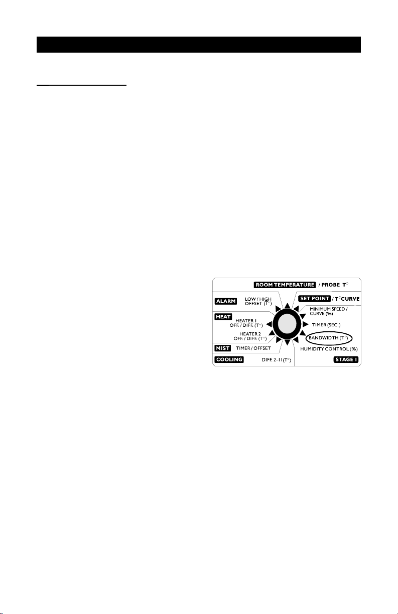
nSet the selection knob to STAGE
1 — BANDWIDTH. The Stage 1
bandwidth is displayed and
flashes.
nPress the push-button. The cur-
rently selected motor type is
displayed, alternating with the
letters"tYP".
nUsetheadjustmentknobtoadjustthemotortypetothedesiredvalue.
nReturn to the Stage1bandwidthdisplay by pressingthepush-button
once again.
MOTOR TYPES
10 TC5-1V10SArev.06
TC5-1V10SA
1
Connecting the Probes
The controller is supplied with one temperature probe connected to input
#1. Uptothreeadditionalprobescanbeconnectedtothecontrollerinorder
to obtain a more accurate reading of the average room temperature and a
fasterreactiontime.
nUseinputs#2,3 and 4 toconnectadditionalprobes,as shown on the
wiringdiagramenclosed.
CAUTION:Probesoperateatlowvoltageandareisolatedfromthesupply.
Besurethat probecablesremain isolatedfromallhigh voltagesources. In
particular,donotroutetheprobecablesthroughthesameelectricalknockout
asothercables. Donotconnecttheshieldfromtheprobecabletoaterminal
ora ground.
Stages 10 and 11 can operate as heating or cooling stages.
ðSet switches # 6 and # 7 to OFF to
use both stages for cooling.
ðSet switch # 6 to ON and switch # 7
to OFF to use Stage 11 for heating
and Stage 10 for cooling.
ðSet switches # 6 and # 7 to ON to
use both stages for heating.
Note that if only one stage is used for heating, it must be Stage 11.
TEMPERATUREPROBES
HEATING / COOLING OPTION
67
ON
Indice


