Asada UE-30 Manuale utente

Wire Lift
Electric Wire Lift
Please read through this manual before operating.
INSTRUCTION MANUAL
ELECTRIC WIRE LIFT
1
WARNING Denotes that incorrect handling can cause death or injury to the user and
others.
In this manual and on the machine, the safety instruction levels are classied into as following three levels.
SAFETY PRECAUTIONS
DEFENITIONS OF THE DANGER, WARNING, CAUTION SYMBOLS
Denotes that incorrect handling can cause user injury or physical damage.
CAUTION
Thank you for selecting Electric Wire Lift.
● Please give this operation manual to anyone who operates this unit.
● For safe and ecient operation any operator should read this manual thoroughly
before operation.
● Do not use this unit for purposes other than originally intended.
● Check the following as soon the unit is delivered:
・ Is the specication same as the ordered product?
・ Has there been any damage or deformation during delivery?
・ Are any accessories missing?
If you have any questions, please contact the store where you have purchased
this unit or our sales department.
(The contents of this manual may be changed without prior notice.)
DANGER Denotes that incorrect handling would cause immediate death or injury to the
user and others.
GENERAL SAFETY INSTRUCTIONS.... 2
SPECIAL SAFETY INSTRUCTIONS ..... 5
PARTS IDENTIFICATION .......................... 6
Name of parts .................................................. 6
Positions of warning label............................. 7
Specication.................................................... 7
Standard Accessories.................................... 8
Optional Accessories..................................... 8
PREPARATION............................................... 9
Assembling...................................................... 9
Horizontal Value ........................................... 10
Use in Step.................................................... 10
Caster ........................................................... 10
Maximum Load Capacity ............................. 11
Aluminum Plate............................................. 12
Extension Adaptor........................................12
Emergency Stop Button ............................... 13
Power Supply ................................................. 13
OPERATION .................................................. 14
Lift Up and Down ........................................ 14
Emergency Stop ............................................ 15
Undo Emergency Stop .............................. 15
Manual Operation........................................ 16
Winding Protection Device ........................ 16
Overload Protection Device ....................... 17
Position of the Wire .................................... 17
Folding .......................................................... 17
MAINTENANCE & SPECTION.................... 18
Daily Inspection ............................................ 18
6 Month Inspection ..................................... 20
How to Adjust Slide Fixed Resin ............... 21
Storage ...................................................... 21
BEFORE REQUESTING REPAIR OR SERVICE
........... 22
CONTENTS

ELECTRIC WIRE LIFT
2
GENERAL SAFETY INSTRUCTIONS
CAUTION
◆ Do not use the unit in a place where has ammable liquid such as
gasoline and thinner or ammable gas.
A spark occurs while operating or turning on/o the switch. It may cause an
explosion or ignition.
◆ Do not operate the unit with wet hands or in the rain.
Handling the electric plug and power switch with wet hands or in the rain, may
cause electric shock.
◆ Please check the wire before the operation.
Do not use the wire with which 10% of the element wires within
1 twist of the wires are cut o, its diameter is less than 3.7mm,
kinked, deformed, or corroded. (Refer to P.18『Daily Inspection』)
◆ Do not remodel the unit.
◆ Do not exceed rated load capacity.
Overload may cause of damaging the aluminum plate, fall of the load, or breaking
the unit.
◆ Do not move the load on the aluminum plate.
The center gravity of the load may deviate and the unit may tumble down.
◆ Do not use the unit on a soft ground or inclined surface.
Operation on the unstable location such as with sand or gravel may cause of
dropping the load, turning over the unit, damage, or injury.
Do not use on a bumpy or slippery ground with a slope or holes.
● Before using the unit, read all safety instructions to use it correctly according to
the instructions.
● Detailed function of the operation is described in each chapter after this.

ELECTRIC WIRE LIFT
3
WARNING
◆ When using the unit, gravity of the load should come at the center of
the aluminum plate.
◆ Do not climb up the unit or set a ladder and put a load on one side of
the mast.
◆ Do not stand under the top board when it's rising.
In case of the load drops, it may cause of injury. Conrm that there are no people
around during the operation.
◆ Do not bring hands or face closer to the part to be driven while
operating.
◆ Do not lift the load without xing.
For preventing a move of the load on the top board, x the load by a belt before
lifting.
◆ Do not operate the unit to swing the load.
◆ Do not leave the unit with lifting up or with an elevated load.
◆ Do not move the load while lifting.
◆ Use the unit in a place where no wires or obstacles overhead.
◆ Do not use the unit on an unstable place such as a bed of a truck.
◆ Do not disassemble the unit except service engineers. Also do not
remodel the unit.
It may cause of injury or trouble by abnormal movement.
◆ Do not let people not involved in the operation stay close to the
unit.
◆ Do not use the unit in strong or gusty winds, or in the rain.
ELECTRIC WIRE LIFT
4
CAUTION
◆ Do not give a strong shock to the unit. Also do not pull the mast
with a force.
◆ Make sure that there is no trouble with the unit by idling two or
three times before use.
Especially when the unit hasn't been used for long time, please idle.
Do not idle without the aluminum plate on the unit.
◆ Use only approved parts for the unit.
◆ Wear an appropriate clothes for the operation.
Wear a helmet, safety shoes, and gloves while operating.
◆ Do not exceed the load capacity or specication.
It may cause of an injury or damage of the unit.
◆ Keep the work space and surroundings clean and tidy.
It will aect not only safe work, but also working eciency.
◆ Do not operate on an unstable location or with unnatural posture.
It may cause of an injury by stumbling.

ELECTRIC WIRE LIFT
5
SPECIAL SAFETY INSTRUCTIONS
WARNING
◆ The unit is a lift for the load. Do not lift people or animal.
◆ Check all the parts before use and conrm whether there is no
damage or lack of the parts.
In case of any damage or lack of the parts, stop using the unit immediately and
repair or change.
◆ Do not load the load on the edge of the aluminum plate.
It may cause of damaging the plate and dropping the load.
◆ Do not use a broken aluminum plate.
◆ Press the emergency stop button and turn o the power supply if
problems occur during operation. Stop using the unit immediately
and contact an authorized repairer.
◆ When overload protection or winding protection is on, do not pull
the trigger of the controller.
It may cause of a breakdown.
◆ Use only the included handle for a manual operation.
Use only approved parts for the unit. Using not standard parts may damage the unit
and cause danger.
◆ Keep away the power cable from objects that are sharp or with heat.
◆ Avoid using with an extension cord unless it is necessary.
Using an inappropriate extension cord may cause of re, getting a shock, or damage
of the unit. In case of necessity of using an extension cord for outside work, use a
cord less than the length of 20m and over 2 m㎡ or more.
◆ Do not ll a vent hole of the motor.
A vent hole of the motor is necessary for preventing from overheating.
◆ Check a level of the lift by a sprit level before use.
◆ Use the unit with casters on a horizontal location.
Using it with casters on a slope or step may cause a serious problem.
◆ Do not move the unit while loading the load.
◆ Use brakes of the slide casters while operating.
ELECTRIC WIRE LIFT
6
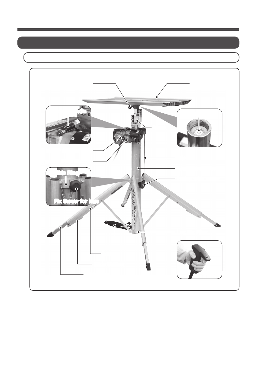
PARTS IDENTIFICATION
Name of parts
Mast
Aluminum Plate
Leg Fix Ring
Platform
Motor & Gear Box
Emergency Stop Button Wire
Slide Button
Legs
Slide Legs
Aluminum Cylinder
Pulley with cover
Manual Handle
Slide Ring
Fix Screw for legs
Sprit Level
Controller
Mast Holding Belt
Explaining with model UE-30 on this instruction manual.

ELECTRIC WIRE LIFT
7
Specication
Positions of warning label
High Voltage Warning Label
(SS0146)
Emergency Stop Button Label
(SS0335)
Motor Warning Label
(SS0336)
Contact Warning Label
(SS0147)
Winding Danger Label
(SS0145)
Top Board Danger Label
(SS0334)
Max Load Capacity Label
(SS0332)
● Please contact us when the labels get dirty or come o and dicult to read.
● Please stick labels on the same place.
Models UE-30 UE-33C UE-37 UE-40C
Code No. UE301 UE331 UE371 UE401
Power Supply 1 phase 220-240V 50/60 Hz
Hoisting Time
(no load) (in seconds) UP 24 / DOWN 23 UP 40 / DOWN 35
Max Load
Capacity
With Cylinder 150 kg 120 kg 120 kg 120 kg
With 4 legs 120 kg N/A 100 kg N/A
Height (Maximum) 3040 ㎜ 3265 ㎜ 3755 ㎜ 3970 ㎜
Height (Minimum) 1090 ㎜ 1193 ㎜ 1155 ㎜ 1240 ㎜
Measurement (Aluminum Board)
745 × 435 ㎜
Measurement (Between Legs)
1010 × 1030 ㎜ 1120 × 1220 ㎜ 1110 × 1110 ㎜ 1150 × 1150 ㎜
Dimension (Storage)
310 × 250 × 1075 ㎜ 330 × 230 × 1170 ㎜ 310 × 250 × 1135 ㎜ 310 × 260 × 1220 ㎜
Weight 26 kg 29 kg 31 kg 34 kg
Noise 95 dB
Controller Cord 3m 4m
Cabtyre Cord 2.8m

ELECTRIC WIRE LIFT
8
Standard Accessories
Optional Accessories
Code No. Models
UE-30 UE-33C UE-37 UE-40C
UE3002 Electric Wire Lift UE-30 ○
UE3302 Electric Wire Lift UE-33C ○
UE3702 Electric Wire Lift UE-37 ○
UE4002 Electric Wire Lift UE-40C ○
UE3079 Extension Adaptor ○ ○
UE3003 Aluminum Plate ○○○○
UE3005 Manual Handle ○○○○
UE3004 Cover for Aluminum Plate ○○○○
IM0444 Instruction Manual ○○○○
Code No. Models
UE-30 UE-33C UE-37 UE-40C
UE3079 Extension Adaptor ※ ○ ○
UE3098 Casters Set ※ ○ ○
※:Maximum load capacity will vary when using the lift with optional accessory.
Use the lift referring to P11 for Maximum load capacity.
ELECTRIC WIRE LIFT
9
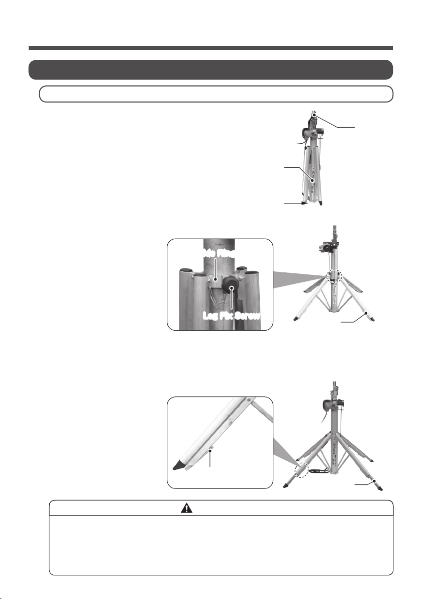
PREPARATION
◆ Use the lift with opening legs full.
Set the legs correctly. Otherwise falling down may occur.
◆ Use the lift with grounding 4 legs.
Otherwise falling down may occur.
Aluminum Cylinder
Mast
holding belt
Ground
Slide Leg
Slide Button
Slide Ring
Leg Fix Screw Leg
CAUTIONS
Assembling
③ Loosen the leg x screw of the slide ring and open the legs.
④ Once fully opened legs, tighten the leg x screw.
⑤ Push the slide buttons and make the legs longer.
Make each leg longer until each all of 4 legs are grounded.
The length of slide legs should be shorter than upper second
red mark from leg edge.
⑥ The slide leg is xed once remove your hand from the slide
button.
① Set the lift on a at and solid ground.
In case the setting position is not stable, cover the
position where the aluminum cylinder is grounded.
② Remove the mast holding belt from the mast.
Questo manuale è adatto per i seguenti modelli
7
Indice
Manuali Sistema di sollevamento popolari di altre marche


Genie
Genie Z-60/34 Manuale utente

Screen Technics
Screen Technics INTERFIT Vertical Up Lift Manuale utente

Mortuary Lift
Mortuary Lift ULTIMATE 1000 Manuale utente

Custom Equipment
Custom Equipment Hy-Brid 3 Series Manuale di programmazione

Custom Equipment
Custom Equipment Hy-Brid Lifts 2 Series Manuale di programmazione

Hy-Brid Lifts
Hy-Brid Lifts HB-P3.6 Manuale di programmazione


