Asante Voyager II User's Manuale utente

1
Voyager II
Megapixel Pan/Tilt IP Camera
User’s Manual
Version 1.0
Content
Content ........................................................................................................................... 1
Packaging Contents ........................................................................................................ 3
System requirements ...................................................................................................... 4
Introduction .................................................................................................................... 5
Features and Advantages ................................................................................................ 5
System Instructions ........................................................................................................ 6
Hard are Installation ..................................................................................................... 9
Camera Setting ............................................................................................................. 10

2
Camera Setting from a Router ..................................................................................... 12
Change the Internet Explorer Setting ........................................................................... 13
Enter the Main Page ..................................................................................................... 14
Camera Main Page ....................................................................................................... 16
System setting .............................................................................................................. 26
Basic Setting ................................................................................................................ 26
System ................................................................................................................. 26
Video/Image ........................................................................................................ 27
Audio ................................................................................................................... 34
User ...................................................................................................................... 35
Network ............................................................................................................... 37
Net ork ........................................................................................................ 37
Wireless ........................................................................................................ 38
Streaming ..................................................................................................... 43
PPPoE .......................................................................................................... 44
DDNS ........................................................................................................... 46
UPnP ............................................................................................................ 47
SMTP Server ................................................................................................ 49
Samba ........................................................................................................... 50
ate/Time ............................................................................................................ 53
IP Filter ............................................................................................................... 54
Application Setting ...................................................................................................... 55
Event .................................................................................................................... 55
Motion etection ................................................................................................ 62
Firmware upgrade ............................................................................................. 63
Factory efault ................................................................................................... 65
Reboot ................................................................................................................. 67
Attachment A: External Alarm ..................................................................................... 68
Attachment B: Band idth Estimation ......................................................................... 68
Attachment C: Troubleshooting and FAQs .................................................................. 71

3
Packaging Contents
The Asante Voyager-II PT IP Camera is provided with the following accessories.
Please contact your dealer if any one of the following is missing.
1. Megapixel PT IP Camera 2. 12V DC power cable
3. Tripod 4. Audio cable
5. Quick guide 6. CD

4
System requirements
ASANTE VOYAGER II PT IP Camera
Internet Environment
LAN 10/100M Ethernet
Wireless LAN 802.11b or 802.11g
Monitor System Requirements
OS support Windo s 2000 Professional SP4, XP Home SP2
Bro ser support Internet Explorer 6.x or later
Hard are CPU: Pentium 4 2.4 GHz or later
Memory: 256 MB (512 MB recommended)
VGA card resolution: 800 x 600 or higher

Introduction
The Voyager II PT IP Camera is a multi-functional stand-alone PT Internet Camera
that can connect to Ethernet, LAN, or any broad-band networks. Unlike traditional
CCTV cameras, the Voyager II PT IP Camera has a built-in CPU and webpage server
to provide users with a mechanism for home security or remote office monitoring
applications. The Voyager II PT IP Camera supports 3GPP real-time video streams
that allow you to control the home or office environment using a 3G mobile phone.
The Voyager II PT IP Camera is easy to install and use. The built-in webpage server
enables you to control the security and property of your home easily when you go
abroad.
Features and Advantages
The Voyager II PT IP Camera is a stand-alone PT Internet Camera. It can operate
smoothly without the need to install additional software or hardware. All you need is a
PC that is equipped with IE browser (6.0 or above) and connect the Internet Camera
to the network to monitor the pre-set places remotely. The Voyager II PT IP Camera
provides you with protection of your personal, home, and property security.
The Voyager II PT IP Camera features:
1/4" CMOS color image sensor to ensure clear and vivid imaging effect;
MPEG4/MJPEG dual video compression mode and dual coding mechanism for
multiple applications;
Support of 3GPP real-time video streams that allow you to control home or
office environment using a 3G mobile phone;
Auto-pan camera with 270°(horizontal) and 135°(vertical) rotation angles and a
maximum of 16 pre-set scan points;
Built-in smart motion detection to monitor abnormal situations automatically and
transmit real-time trigger command actively as preset;
Built-in webpage server that allows easy control via the Internet;
Dynamic IP domain name support for use of the product at locations where fixed
IP is not available;
Access setting by level to ensure security and protection of life and properties;
Elegant style suitable for homes, studios, offices, clinics, and retail shops.

6
System Instructions
1. DC po er cable: The DC input connector has a socket to connect the product to a
po er source.
2. Ethernet connector: A RJ-45 connector is provided for connection to the 10Base-T
Ethernet cable or 100 Base-T High Speed Ethernet cable. This port can
automatically detect or coordinate the transmission rate of the net ork.
3. Use a video/audio output cable for external video/audio transmission if required.
Wiring of the product
C Power
Plug the po er cable in the po er socket on the product.
Tripod
The product can be fixed on the all (Fig. 1) or hung from the ceiling (Fig. 2).
When using the attached plastic anchor and scre s to fix the product, make sure that
no steel bars or po er cables exist behind the position here the product is to be fixed.
Some alls or ceilings may not be strong enough to support the tripod and the product.
Pay attention during installation to avoid injury that might be brought about due to
falling of the product.

7
Note: The horizontal angle is important when you hang the product from the ceiling.
Excessive inclination may bring about abnormal rotation of the camera lens.
Fixed on a wall (Fig. 1)
Fixed on a ceiling (Fig. 2)
MIC in/Audio Out
Plug the Audio cable to the back of the camera.
The Red connector is for Microphone input.
The Green connector is for Speaker out for connection to a sound amplifier or an
amplified speaker.
LAN Socket
Insert your LAN cable in the LAN socket.

8
External alert bus ( I/ O)
For more information about DI/DO, refer to Attachment A.
Reset to factory settings
After turning on the machine, press in this hole for 5 seconds using a sharp object to
reset to factory settings.
Built-in microphone
The product is provided ith built-in microphone pickup function. Don't block this
hole if you ant to use this function to acquire the best audio response.
Link LE and Event LE
1. Link LED: The green LED lights up hen you transmit images after turning on
the machine.
2. Event LED: The green LED flashes hen motion or alert detection is
implemented after you turn on the machine.
Focus knob
You can rotate the focus knob clock ise or anticlock ise to acquire the sharpest
image.
Focus knob

9
Hardware Installation
You can install the product on your desk or use the attached tripod to hang it from the
all or ceiling. (The product is provided ith image flip function. Refer to the
“Control Panel” for more information.)
1. Connect to the LAN cable
Plug one end of your LAN cable in the LAN socket on the back of the camera and
connect the other end to the net ork that you ant to access to.
2. Connect to the power source
Plug one end of the attached po er cable in the po er socket of the product and
connect the other end to the AC po er source. When the product has been connected
and turned on, the Pan/Tile camera turns to the original point automatically and the
LED: Event status lights green. When any link to the net ork is detected, the LED:
Link status flashes green.
Note 1: You can install the product quickly with reference to the quick guide attached to the
product.
You can specify three LED statuses by setting: 1.ON; 2.OFF; 3.Flash. For more information about
setting of LED status, refer to the “System Setting”.
Note 2: on't install the camera at an oblique angle to avoid disrupted operation of the machine.
Confirm the position for installation of the camera
Pluck in LAN socket
Connect to the po er supply and check that the LED functions normally.
10
Camera Setting
After the hard are has been installed, insert the attached CD in the computer and
execute IP FINDER.EX follo ing the steps belo to search and change the IP
address of the camera.
1. Start the machine.
Execute the IP Finder.exe from the attached CD.
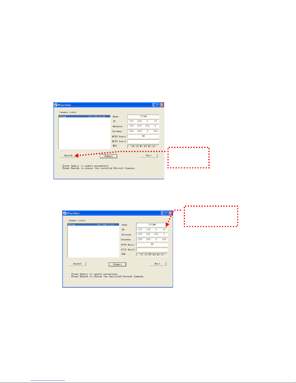
2. Search the camera (Search)
Search the product from your LAN. The factory IP setting 192.168.0.20 appears
on the screen.
3. Changing the IP address and related settings for the net ork environment
When you find the camera, click it and the settings appear on the right side.
Change the settings for the ne net ork environment you need.
※ You must enter ne settings in the IP, Netmask and Gate ay fields and keep
the settings in other fields unchanged.
4. Submit data (Submit)
Click Submit to validate ne settings.
1. Click Search to
find the IPCAM on
the LAN.
2. Enter the settings for the
ne net ork environment
you need.
Questo manuale è adatto per i seguenti modelli
1
Indice
Altri manuali Asante Telecamera IP


