CLARITY 16C/D/E/S Product Manual SECTION 2
10 117020 Rev C
SECTION 2 Operation
2.1 Description of operation
Vertical motion of the platform is controlled by the three (3) operating switches located
in the platform and at the landings. While any switch is in use, the other switches are
disabled. These are constant-pressure type switches, meaning that the platform stops
when the switches are released.
A door at each landing permits passengers to enter and exit the platform. Each door is
equipped with an electric lock that prevents the door from being opened while the
platform is away from the given landing, ensuring the safety of those inside and outside
the platform. Both doors are self-closing.
Two parallel-connected hydraulic cylinders raise and lower the platform. When the "Up"
circuit is energized, an electric motor operates a hydraulic pump which provides
pressurized hydraulic fluid to the cylinders, causing the cylinder rods to extend and raise
the platform. When the "Down" circuit is energized, a hydraulic valve is opened to allow
a controlled, gravity-driven descent. It takes approximately 45 seconds for the platform
to travel in either direction through its maximum travel range of 168 inches (14 feet).
The lift is equipped with standard battery backup that allows the platform to be operated
up and down at least five (5) cycles in the event of a power outage. Additionally, the lift
is equipped with a manual lowering pull handle that can be used to lower the platform in
an emergency. Use of the override pull handle is restricted to authorized personnel
only. The platform will descend at a controlled speed as long as the handle is pulled
until it rests at the lower landing.
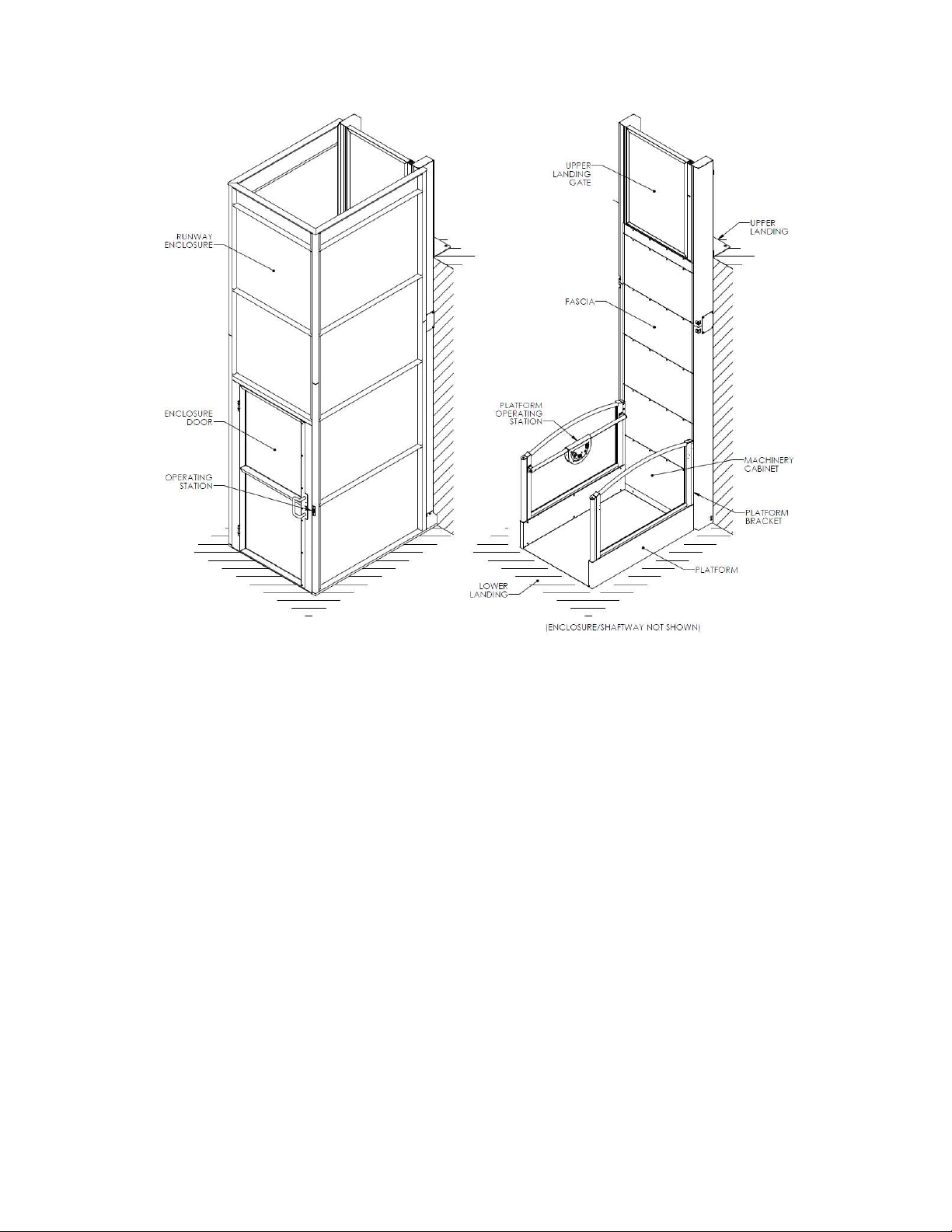
The drive unit and electrical controller are located at the base of the machine cabinet,
behind the bottom fascia panel. Equipment at this location includes the motor, pump,
power supply, batteries, controller circuit board, and motor relay.