ascon M3 Series Manuale utente
Temperature
Controller
1/16 DIN - 48 x 48
M3 line cc
User manual • M.I.U.M3 -4/03.01 • Cod. J30-478-1AM3 IE
ASCON spa
20021 Bollate
(Milano) Italy
via Falzarego, 9/11
Tel. +39 02 333 371
Fax +39 02 350 4243
http://www.ascon.it
e-mail [email protected]
ASCON spa
ISO 9001
Certified
UL
CUS
LISTED
Temperature
Controller
1/16 DIN - 48 x 48
M3 line cc
274.8
275.0
1
2
3
3
RUN
UL
CUS
LISTED

2
Information
cc
NOTES
ON ELECTRIC
SAFETY AND
ELECTROMAGNETIC
COMPATIBILITY.
Please, read carefully these instructions before proceeding with
the installation of the controller.
Class II instrument, real panel mounting.
This controller has been designed with compliance to:
Regulations on electrical apparatus (appliance, systems and installa-
tions) according to the European Community directive 73/23 CEE amend-
ed by the European Comunity directive 93/68 CEE and the Regulations
on the essential protection requirements in electrical apparatus EN 61010-
1 (IEC 1010 - 1) : 90 +A1:92 + A2:95.
Regulations on Electromagnetic Compatibility according to the
European Community directive n089/336/CEE, amended by the European
Community directive n° 92/31/CEE and the following regulations:
Regulations on RF emissions
EN50081 - 1 residential environments
EN50081 - 2 industrial environments
Regulation on RF immunity
EN500082-2 industrial equipment and system
Itisimportanttounderstandthatit’sresponsibility of the installer to ensure
the compliance of the regulations on safety requirements and EMC.
The device has no user serviceable parts and requires special equipment
and specialised engineers. Therefore, a repair can be hardly carried on
directly by the user. For this purpose, the manufacturer provides techni-
cal assistance and the repair service for its Customers.
Please, contact your nearest Agent for further information.
All the information and warnings about safety and electromagnetic
compatibility are marked with the Bsign, at the side of the note.
3
Table of contents
1INSTALLATION.............................................................................................................................Page 4
2ELECTRICAL CONNECTIONS.......................................................................................Page 8
3PRODUCT CODING................................................................................................................Page 16
4OPERATIONS................................................................................................................................Page 20
5AUTOMATIC TUNE.................................................................................................................Page 38
6SPECIAL FUNCTIONS........................................................................................................Page 39
7TECHNICAL SPECIFICATIONS.....................................................................................Page 44
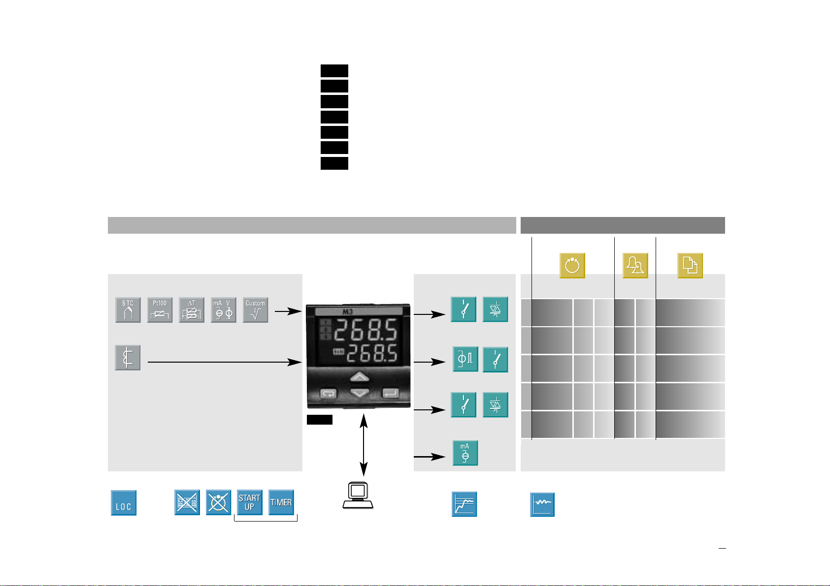
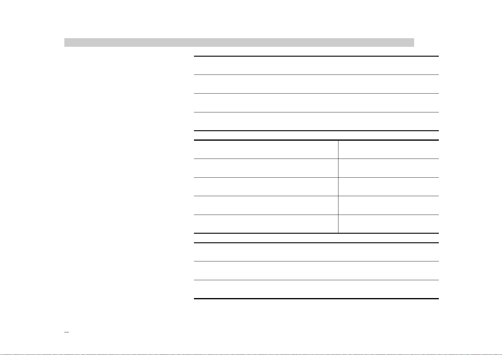
Main universal input
Control Alarms Retransmission
Resources
OP1PV
AUX
OP2
OP4
(option)
Auxiliary input (option)
OP3
Operating Modes
PV/SP
2
Single
OP2 OP1 OP3 OP4
action
3
Double
OP1 OP3 OP2 OP4
action
4
Double
OP1 OP2 OP3 OP4
action
5
Double
OP2 OP3 OP1 OP4
action
1
Single
OP1 OP2 OP3 OP4
action
M3
Modbus RS485
Parameterisation
Supervision
(option)
Fuzzy tuning
with automatic selection
One shot
Auto tuning One shot
Natural frequency
TABLE OF CONTENTS
Setpoint Special functions
(option)
4
1 - Installation
1INSTALLATION
Installation must only be carried
out by qualified personnel.
Before proceeding with the instal-
lation of this controller, follow the
instructions illustrated in this man-
ual and, particularly the installation
precautions marked with the B
symbol, related to the European
Community directive on electrical
protection and electromagnetic
compatibility.
B
To prevent hands or metal touch-
ing parts that may be electrically
live, the controllers must be
installed in an enclosure and/or
in a cubicle.
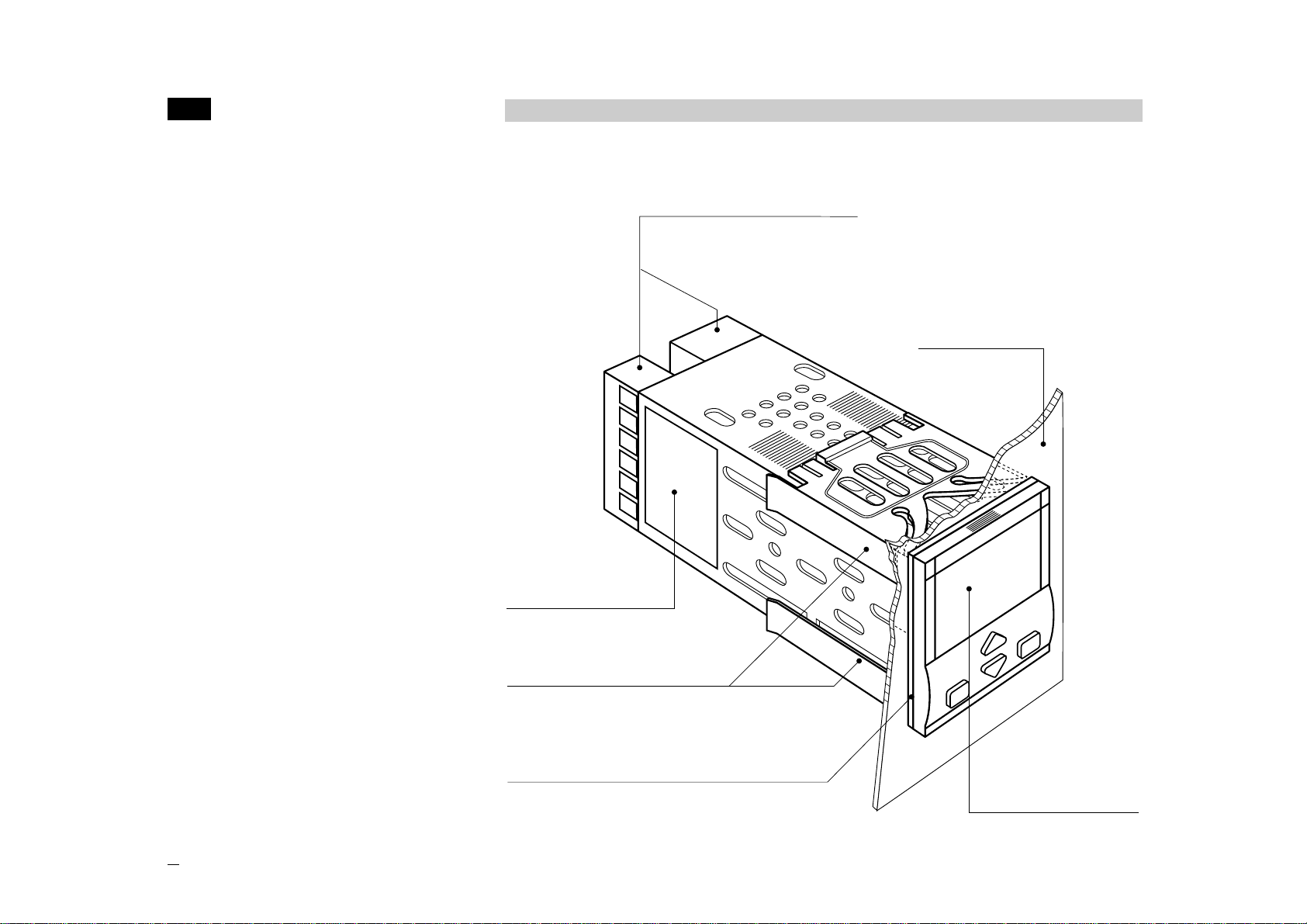
1.1 GENERAL DESCRIPTION
IP 20 Termination Unit
EN61010 - 1 (IEC1010 - 1)
Product code label
Sealing front panel gasket
Mounting clamps
Panel surface
Front panel
IP65 protection
EN 650529 (IEC 529)
5
1 - Installation
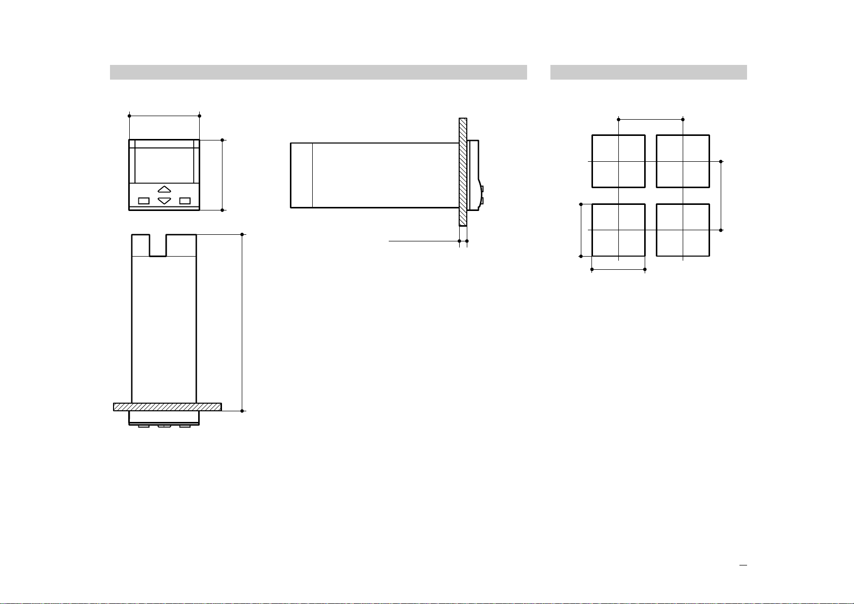
1.2 DIMENSIONAL DETAILS
48mm
1.89in
120mm
4.72in
48mm
1.89in
20mm max
0.79in max
1.3 PANEL CUT-OUT
65mm min
2.56 in min
45+0.6 mm
1.78+0.023 in
45+0.6 mm
1.78+0.023 in
65mm min
2.56 in min
6
1 - Installation
Special conditions
MAltitude > 2000 m
TTemperature >50°C
%Rh Humidity > 95 %
PConducting atmosphere Use filter
Warm up
Use forced air ventilation
Use 24V~supply version
Suggestions
Forbidden Conditions D
CCorrosive atmosphere
EExplosive atmosphere
Operating conditions
MAltitude up to 2000 m
TTemperature 0…50°C
%Rh Relative humidity 5…95 % non-condensing
1.4 ENVIRONMENTAL RATINGS B
7
1 - Installation
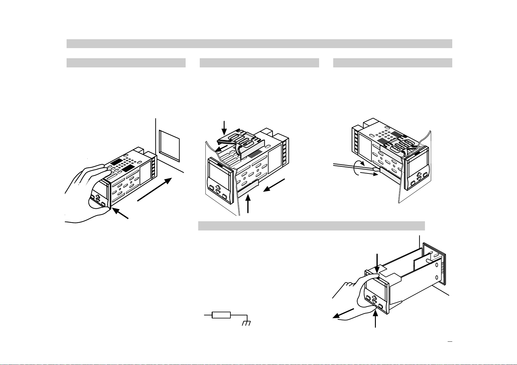
1.5.1 INSERT THE INSTRUMENT
1Prepare panel cut-out
2Check front panel gasket posi-
tion
3Insert the instrument through
the cut-out
UL note
[1] For Use on a Flat Surface of
a Type 2 and Type 3 ‘raintight’
Enclosure.
1.5.2 INSTALLATION SECURING
1Fit the mounting clamps
2Push the mounting clamps
towards the panel surface to
secure the instrument
1
3
2
1.5.3 CLAMPS REMOVING
1Insert the screwdriver in the clips
of the clamps
2Rotate the screwdriver
1
2
1.5.4 INSTRUMENT UNPLUGGING B
1Push and
2pull to remove the instrument
Electrostatic discharges can dam-
age the instrument
Before removing the instrument the
operator must
discharge himself
to ground
1
2
1
1MΩ
1.5 PANEL MOUNTING [1]
1
1
1
2
8
2 - Electrical connections
2ELECTRICAL
CONNECTIONS
UL note
[1] Use 60/70 °C copper (Cu) con-
ductor only.
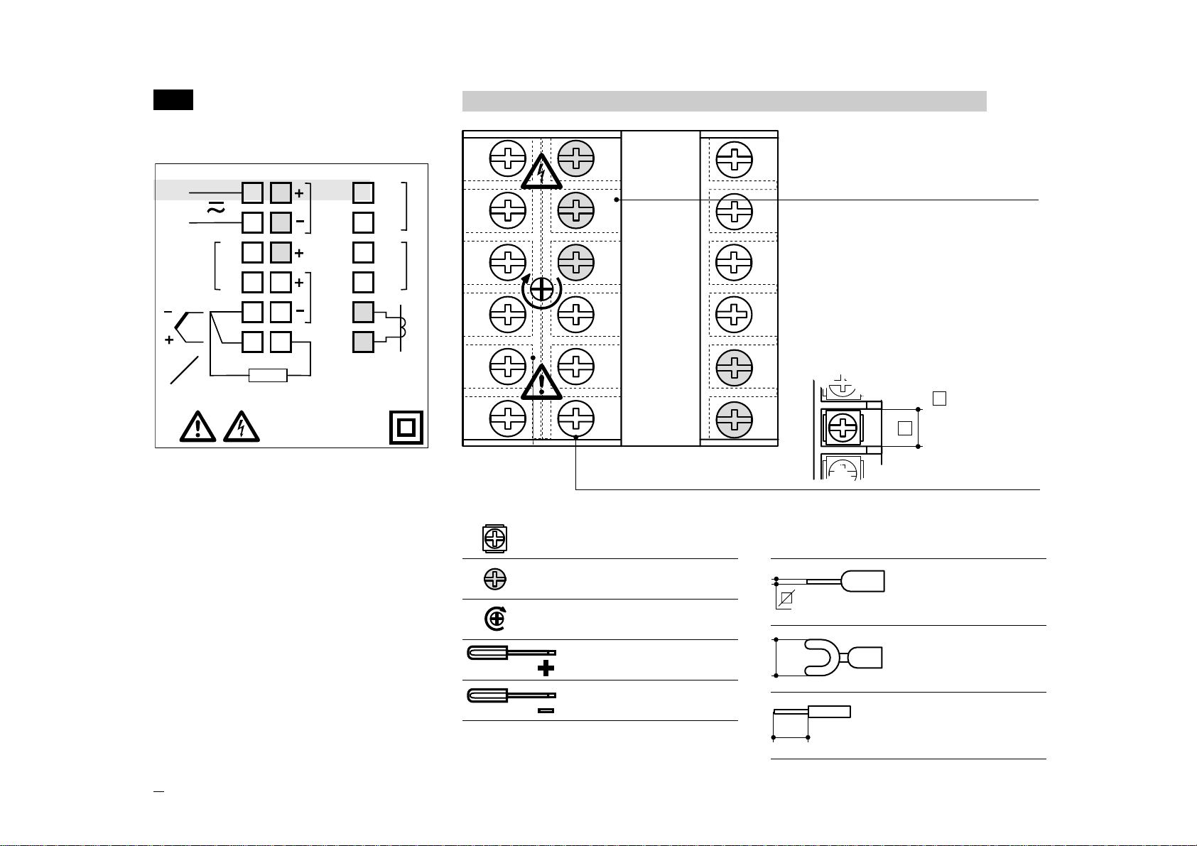
2.1 TERMINATION UNIT [1] B
18 screw terminals
Option terminals
Holding screw 0.5 Nm
Pin connector
q1.4 mm
0.055 in max
Ø
Fork-shape
AMP 165004
Ø 5.5 mm - 0.21 in
Stripped wire
L 5.5 mm - 0.21 in
Terminals
L
0,5
Nm
6
5
4
3
2
1
12
11
10
9
8
7
16
15
18
17
14
13 Rear
terminal
cover
Cable size
1 mm2
18 AWG
5.7 mm
0.22 in
Positive screw
driver PH1
Negative screw
driver 0,8 x 4 mm
6
5
4
3 9
2 8
1 7
12
11
10
18
17
16
15
14
13
18V
OUT
RTD
N
L
B
TA OP3
NO
C
RS485
(OP4)
OP2-R
NO
C
NO
C
OP1
OP2-L
b
TC
mA
mV
A
9
2 - Electrical connections
PRECAUTIONS B
Despite the fact that the instrument
has been designed to work in an
harsh and noisy environmental
(level IV of the industrial standard
IEC 801-4), it is recommended to
follow the following suggestions.
A
All the wiring must comply with the
local regulations.
The supply wiring should be rout-
ed away from the power cables.
Avoid to use electromagnetic con-
tactors, power Relays and high
power motors nearby.
Avoid power units nearby, espe-
cially if controlled in phase angle
Keep the low level sensor input
wires away from the power lines
and the output cables.
If this is not achievable, use shield-
ed cables on the sensor input, with
the shield connected to earth.
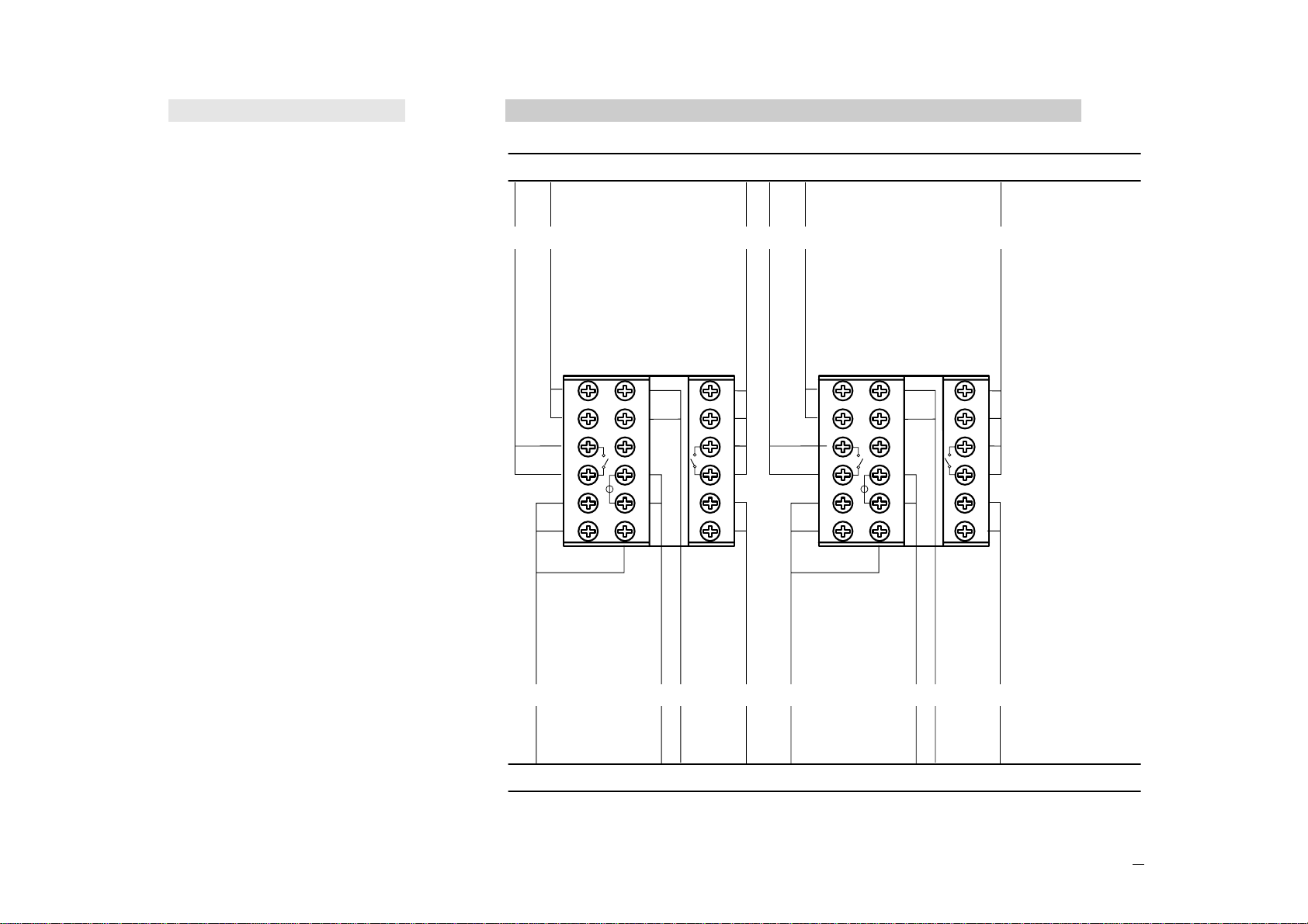
2.2 PRECAUTIONS AND ADVISED CONDUCTOR COURSE B
Conduit for supply and output cables
Conduit for low level sensor cables
BB
6
5
4
3
2
1
12
11
10
9
8
7
L
N
A
CED
16
15
B B
6
5
4
3
2
1
12
11
10
9
8
7
L
N
A
CED
16
15
B
18
17
14
13
18
17
14
13
C C
A= Supply
B= Outputs
C= Analog inputs
D= Analogue
Output
Serial Comm.s
E= SSR drive
output
Indice
Altri manuali ascon Regolatori di temperatura


