
ATH Single Lift 35M Manuale utente

OPERATING INSTRUCTIONS
ATH Single Lift 35M

® Copyright ATH-Heinl GmbH & Co. KG, 2019, All rights reserved / Misprints and technical changes reserved / As of: 2019-01
Manufacturer ATH-Heinl GmbH & CO.KG
- 2 -
Contents
1.0 INTRODUCTION ................................................................................................................... - 3 -
1.1 General Information ........................................................................................................... - 3 -
1.2 Description ........................................................................................................................ - 4 -
1.3 Operation.......................................................................................................................... - 6 -
1.4 Technical Data .................................................................................................................. - 8 -
1.5 Scale Drawing ................................................................................................................. - 10 -
2.0 INSTALLATION ................................................................................................................... - 12 -
2.1 Transport & Storage Conditions ........................................................................................ - 12 -
2.2 Unpacking the machine .................................................................................................... - 12 -
2.3 Delivery Contents ............................................................ Fehler! Textmarke nicht definiert.
2.4 Location .......................................................................................................................... - 14 -
2.5 Fixing ............................................................................................................................. - 15 -
2.6 Electrical Connection ........................................................................................................ - 15 -
2.7 Pneumatic Connection ...................................................................................................... - 15 -
2.8 Hydraulic Connection ....................................................................................................... - 16 -
2.9 Assembly ........................................................................................................................ - 16 -
2.10 Completion of Work ...................................................................................................... - 22 -
3.0 OPERATION ....................................................................................................................... - 24 -
3.1 Operating Instructions ..................................................................................................... - 24 -
3.2 Basic Information ............................................................................................................ - 25 -
4.0 MAINTENANCE ................................................................................................................... - 26 -
4.1 Consumables for installation, maintenance and servicing..................................................... - 26 -
4.2 Safety Regulations for Oil ................................................................................................. - 27 -
4.3 Notes ............................................................................................................................. - 28 -
4.4 Maintenance or Service Plan ............................................................................................. - 28 -
4.5 Troubleshooting / Error Display and Solutions .................................................................... - 29 -
4.6 Maintenance and Service Instructions ................................................................................ - 31 -
4.7 Disposal .......................................................................................................................... - 32 -
5.0 EG-/EU-KONFORMITÄTSERKLÄRUNG / EC-/EU-DECLARATION OF CONFORMITY...................... - 33 -
6.0 APPENDIX .......................................................................................................................... - 34 -
6.1 Pneumatic circuit diagram ................................................................................................ - 34 -
6.2 Electric circuit diagram ..................................................................................................... - 35 -
6.3 Hydraulic circuit diagram .................................................................................................. - 36 -
7.0 WARRANTY CARD ............................................................................................................... - 37 -
7.1 Scope of the Product Warranty ......................................................................................... - 38 -
8.0 INSPECTION LOG ............................................................................................................... - 39 -
8.1 Installation and Handover Log .......................................................................................... - 40 -
8.2 Inspection Plan ................................................................................................................ - 41 -
8.3 Visual inspection (authorised expert) ................................................................................. - 42 -
9.0 SPARE PART BOOK ............................................................................................................. - 46 -
10.0 NOTES ............................................................................................................................... - 62 -
® Copyright ATH-Heinl GmbH & Co. KG, 2019, All rights reserved / Misprints and technical changes reserved / As of: 2019-01
Manufacturer ATH-Heinl GmbH & CO.KG
- 3 -
1.0 INTRODUCTION
1.1 General Information
THESE INSTRUCTIONS ARE AN INTEGRAL PART OF THE MACHINE.
THEY MUST BE READ AND UNDERSTOOD BY THE USER.
NO LIABILITY IS ASSUMED FOR ANY DAMAGES CAUSED BY FAILURE TO
FOLLOW THESE INSTRUCTIONS OR THE VALID SECURITY PROVISIONS.
WARNING: Follow the instructions to prevent injury or damage.
TIP: Provides more information on functionality and tips for using the device efficiently.
Appropriate protective clothing must be worn for all work on the described system.

® Copyright ATH-Heinl GmbH & Co. KG, 2019, All rights reserved / Misprints and technical changes reserved / As of: 2019-01
Manufacturer ATH-Heinl GmbH & CO.KG
- 4 -
1.2 Description

® Copyright ATH-Heinl GmbH & Co. KG, 2019, All rights reserved / Misprints and technical changes reserved / As of: 2019-01
Manufacturer ATH-Heinl GmbH & CO.KG
- 5 -
1. Lifting column
The lifting carriage is guided by rollers as it moves up and down the lifting column.
The hydraulic lifting cylinder and the lifting chain are also located here.
2. Lifting carriage
The lifting carriage supports the arm (load bearing equipment). It is lifted and lowered by the
hydraulic cylinder by means of chains; it is guided in the column by rollers.
3. Arm
The adjustable support arm and support plate are attached here. The length of the arm
can be adjusted.
4. Drive kit
Serves to drive and position the lift. The procedure may only be carried out when empty without a
load.
5. Control box
The complete electrical control system is located here. All buttons are protected by a front ring in
order to prevent them being pressed accidentally. Furthermore, all movements are immediately
stopped when the buttons are released (dead man’s control).
6. Hydraulic unit
The hydraulic oil is fed from the tank to the lifting cylinder by a gear pump driven by an electric
motor. The lowering valve allows the oil to flow back into the tank.
7. Base frame
Serves to stabilise the lift and contains the front rollers which drive the lift.
8. Release magnet
Electromagnet for releasing the safety catch during the lowering process.
The safety catch prevents the lift from lowering autonomously in the case of an error.

® Copyright ATH-Heinl GmbH & Co. KG, 2019, All rights reserved / Misprints and technical changes reserved / As of: 2019-01
Manufacturer ATH-Heinl GmbH & CO.KG
- 6 -
1.3 Operation
1. Lockable main switch
To switch the lift on and off and
to prevent operation by
unauthorised persons.
2. Operating light
Indicates whether the lift is in operation.
3. Lift button
To raise the lift.
4. Lower button
To lower the lift.
5. Park button
To park and continue to lower the lift
after it has reached the CE stop.
6. Emergency stop button
To switch the lift off in
dangerous situations.
7. Override button
Overrides the chain emergency off switch
where necessary.
8. Alarm
Warning signal when the CE stop is reached.

® Copyright ATH-Heinl GmbH & Co. KG, 2019, All rights reserved / Misprints and technical changes reserved / As of: 2019-01
Manufacturer ATH-Heinl GmbH & CO.KG
- 7 -
Safety instructions
HAZARD NOTE
1. The danger zone must be kept
clear when lifting and lowering
2. If there is a danger of the vehicle
falling, you must leave the danger
zone immediately
WARNING NOTE
3. Lift may only be operated by
trained personnel.
4. Ensure there are no obstacles
when lowering
5. Prevent the lifted vehicle from
swaying significantly
6. Always ensure that the lifted
vehicle is secured against
slipping.
7. Changes to the lift of any kind are
not permitted
8. Leave the danger zone when
lowering the lift
9. Work on electrical components
may only be performed by
authorised electricians.
10. Do not work on damaged lifts
11. Only authorised persons are
allowed to enter the danger zone.
GUIDING PRINCIPLES
12. Read and understand the
operating instructions before
operating the lift
13. Do not clean the lift under running
water.
14. Do not use any paint-dissolving or
aggressive detergents

® Copyright ATH-Heinl GmbH & Co. KG, 2019, All rights reserved / Misprints and technical changes reserved / As of: 2019-01
Manufacturer ATH-Heinl GmbH & CO.KG
- 8 -
1.4 Technical Data
The factory-set working pressure is adjusted to the maximum power rating. The pressure relief
valve must not be manipulated. Changing the settings can lead to serious damage.
If the indicated rated load cannot be lifted, please contact our
service team.
Model ATH Single Lift 35M
Load capacity 3,500 kg
Lifting time (2,000 kg) 40 s
Lowering time (2,000 kg) 45 s
Electrical system 1/230V/50 Hz or 3/400V/50 Hz
Lifting height 100-1850 mm
Control voltage DC24V
Motor 2.2 KW or 2.6 KW
Upstream fuse 1 C 16 A / 3 C 16 A
Connection cable Min. 3 x 1.5 mm² or 5 x 2.5 mm²
Protection type IP 43
Working pressure ² Approx. 120 bar
Recommended hydraulic oil
Summer: HVLP
-
D 46 (e.g.: ENI Precis HVLP
-
D 46)
Winter: HVLP-D 32
Oil quantity Approx. 6 l
Permissible sound level ≤ 76 dB
Weight 1,300 kg

® Copyright ATH-Heinl GmbH & Co. KG, 2019, All rights reserved / Misprints and technical changes reserved / As of: 2019-01
Manufacturer ATH-Heinl GmbH & CO.KG
- 9 -
Load distribution
Q
Total weight of the
vehicle
P1
Max 2/5 x Q
P2
Max 3/5 x Q
Load
distribution
2/3
A
Min. 1,000 mm ²
² The load capacity of the lift is reduced at lesser distances. Please consult the manufacturer in such
cases, as well as in all other cases not foreseen in these instructions.
® Copyright ATH-Heinl GmbH & Co. KG, 2019, All rights reserved / Misprints and technical changes reserved / As of: 2019-01
Manufacturer ATH-Heinl GmbH & CO.KG
- 10 -
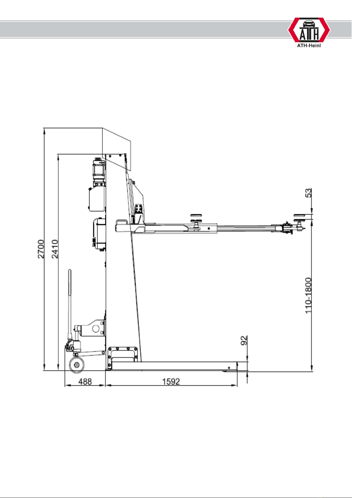
1.5 Scale Drawing
Indice
Altri manuali ATH Sistema di sollevamento


Manuali Sistema di sollevamento popolari di altre marche


Genie
Genie Z-60/34 Manuale utente

Screen Technics
Screen Technics INTERFIT Vertical Up Lift Manuale utente

Mortuary Lift
Mortuary Lift ULTIMATE 1000 Manuale utente

Custom Equipment
Custom Equipment Hy-Brid 3 Series Manuale di programmazione

Custom Equipment
Custom Equipment Hy-Brid Lifts 2 Series Manuale di programmazione

Hy-Brid Lifts
Hy-Brid Lifts HB-P3.6 Manuale di programmazione


