ATH M126 Manuale utente

OPERATING INSTRUCTIONS
ATH M126

® Copyright ATH-Heinl GmbH & Co. KG, 2019, All rights reserved / Misprints and technical changes reserved / As of: 2019-03
Manufacturer ATH-Heinl GmbH & CO.KG
- 2 -
Contents
1.0 INTRODUCTION ................................................................................................................... - 3 -
1.1 General Information ........................................................................................................... - 3 -
1.2 Description ........................................................................................................................ - 4 -
1.3 Operation.......................................................................................................................... - 6 -
1.4 Technical Data ................................................................................................................ - 15 -
1.5 Scale Drawing ................................................................................................................. - 15 -
2.0 INSTALLATION ................................................................................................................... - 16 -
2.1 Transport & Storage Conditions ........................................................................................ - 16 -
2.2 Unpacking the machine .................................................................................................... - 17 -
2.3 Delivery Contents ............................................................................................................ - 17 -
2.4 Location .......................................................................................................................... - 18 -
2.5 Fixing ............................................................................................................................. - 19 -
2.6 Electrical Connection ........................................................................................................ - 19 -
2.7 Pneumatic Connection ...................................................................................................... - 19 -
2.8 Hydraulic Connection ....................................................................................................... - 20 -
2.9 Assembly ........................................................................................................................ - 20 -
2.10 Completion of Work ...................................................................................................... - 22 -
3.0 OPERATION ....................................................................................................................... - 23 -
3.1 Operating Instructions ..................................................................................................... - 23 -
3.2 Basic Information ............................................................................................................ - 24 -
4.0 MAINTENANCE ................................................................................................................... - 25 -
4.1 Consumables for installation, maintenance and servicing..................................................... - 25 -
4.2 Safety Regulations for Oil ................................................................................................. - 26 -
4.3 Notes ............................................................................................................................. - 27 -
4.4 Maintenance or Service Plan ............................................................................................. - 27 -
4.5 Troubleshooting / Error Display and Solutions .................................................................... - 28 -
4.6 Maintenance and Service Instructions ................................................................................ - 29 -
4.7 Disposal .......................................................................................................................... - 30 -
5.0 EG-/EU-KONFORMITÄTSERKLÄRUNG / EC-/EU-DECLARATION OF CONFORMITY...................... - 31 -
6.0 APPENDIX .......................................................................................................................... - 32 -
6.1 Pneumatic circuit diagram ................................................................................................ - 32 -
6.2 Electric circuit diagram ..................................................................................................... - 32 -
6.3 Hydraulic circuit diagram .................................................................................................. - 33 -
7.0 WARRANTY CARD ............................................................................................................... - 34 -
7.1 Scope of the Product Warranty ......................................................................................... - 35 -
8.0 INSPECTION LOG ............................................................................................................... - 36 -
8.1 Installation and Handover Log .......................................................................................... - 37 -
8.2 Inspection Plan ................................................................................................................ - 38 -
8.3 Visual inspection (authorised expert) ................................................................................. - 39 -
9.0 SPARE PART BOOK ............................................................................................................. - 43 -
10.0 NOTES ............................................................................................................................... - 57 -
® Copyright ATH-Heinl GmbH & Co. KG, 2019, All rights reserved / Misprints and technical changes reserved / As of: 2019-03
Manufacturer ATH-Heinl GmbH & CO.KG
- 3 -
1.0 INTRODUCTION
1.1 General Information
THESE INSTRUCTIONS ARE AN INTEGRAL PART OF THE MACHINE.
THEY MUST BE READ AND UNDERSTOOD BY THE USER.
NO LIABILITY IS ASSUMED FOR ANY DAMAGES CAUSED BY FAILURE TO
FOLLOW THESE INSTRUCTIONS OR THE VALID SECURITY PROVISIONS.
WARNING: Follow the instructions to prevent injury or damage.
TIP: Provides more information on functionality and tips for using the device efficiently.
Appropriate protective clothing must be worn for all work on the described system.
® Copyright ATH-Heinl GmbH & Co. KG, 2019, All rights reserved / Misprints and technical changes reserved / As of: 2019-03
Manufacturer ATH-Heinl GmbH & CO.KG
- 4 -
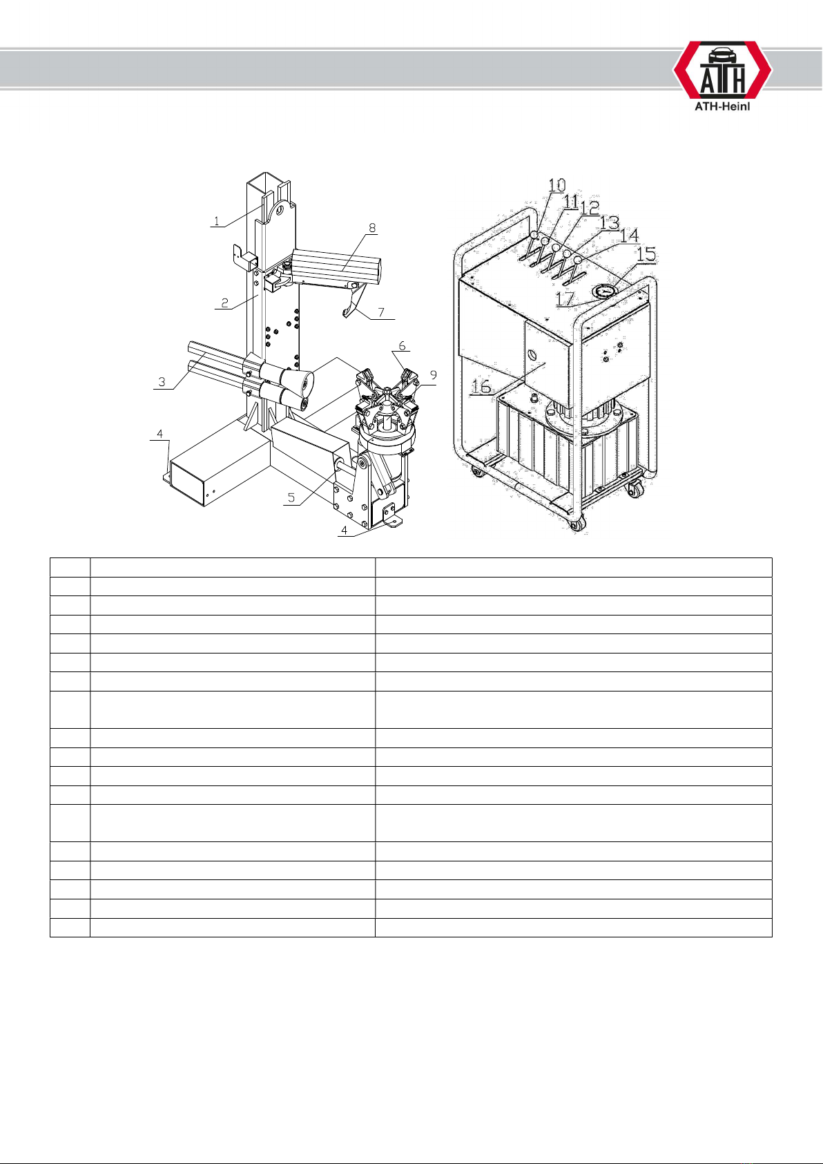
1.2 Description
1 Lifting column Carries the lifting carriage
2 Lifting carriage Holder for assembly tools
3
Assembly rollers
For mounting or removing tyres
4
Mounting bracket
For fixing the machine to the floor
5 Hydraulic cylinder For swivelling the clamping arms
6 Clamping jaws Clamping mechanism
7 Mounting finger For mounting or removing tyres
8
Swivel arm
For the mounting finger, depending on whether this is
used or not.
9 Chuck Mechanism for swivelling and turning the wheel
Control box Hydraulic unit with operating lever
10 Control lever for mounting finger For changing the angle of the mounting finger
11
Control lever for lifting carriage
For lifting and lowering the lifting carriage
12
Control lever for swivelling the chuck
For swivelling the chuck into receiving or working
position
13 Control lever for rotating the chuck For rotating the chuck
14
Control lever for clamping
For clamping the wheel
15
Manometer
Displays the current operating pressure
16 Control box Contains all electrical components
17 Emergency stop For switching off the machine in an emergency

® Copyright ATH-Heinl GmbH & Co. KG, 2019, All rights reserved / Misprints and technical changes reserved / As of: 2019-03
Manufacturer ATH-Heinl GmbH & CO.KG
- 5 -
Operating the tyre changer
1 Control unit for opening and closing the clamping jaws.
2 Control unit for rotating the clamping jaws in a clockwise or counter clockwise direction
3 Control unit for swivelling the clamping jaws
4 Control unit for lifting and lowering the lifting carriage
5
Control unit for the hydraulic mounting finger
2
1
4
4
3

® Copyright ATH-Heinl GmbH & Co. KG, 2019, All rights reserved / Misprints and technical changes reserved / As of: 2019-03
Manufacturer ATH-Heinl GmbH & CO.KG
- 6 -
1.3 Operation
1.3.1 Review of the different functions
Before using the tyre changer, control and check all functions with the operating part to ensure the
machine is working properly. This should be done before each mounting process.
WARNING!
When operating the tyre changer, pay attention to all moving parts. Make
sure there is enough safety clearance so that the moving parts do not contact
you. Make sure there are no other people in the work area.
WARNING!
Always keep enough safety clearance when loosening the mounting arm so
that it does not tilt outwards under tension.
WARNING!
Ensure that there are no persons or objects in the working area of the
machine.
WARNING!
When closing the chuck, the process must be stopped immediately when the
minimum position is reached.
When tightening the rim, stop immediately when the maximum pressure is
reached. For aluminium rims, check the clamping pressure and set it lower if
required.
Failure to comply with this instruction may result in serious damage to the
tyre changer.
1.3.2 Precautions during tyre mounting
Before mounting the tyre, the following precautions must be observed:
Only mount undamaged, clean, dry rims and tyres that are in good condition.
Remove old balance weights.
Check rim and tyre for damage, especially aluminium rims. Do not mount if damaged.
Check that the rim and tyre size match.
Before dismantling, let all air out of the tyre.
Before mounting, coat the rim and tyre well with tyre lubricant to avoid damage.
Always use a new valve.
The tyre changer is not splash-proof, so do not clean wheels on the machine with water jets.
® Copyright ATH-Heinl GmbH & Co. KG, 2019, All rights reserved / Misprints and technical changes reserved / As of: 2019-03
Manufacturer ATH-Heinl GmbH & CO.KG
- 7 -
1.3.3. Operating the tyre changer
This instruction manual only details the function of the machine; it does not replace professional training
and qualification of operating personnel.
WARNING!
All tyre changers have movable or adjustable controls. It is essential to ensure
that the operator always finds a working position where he can safely track
and view all work steps.
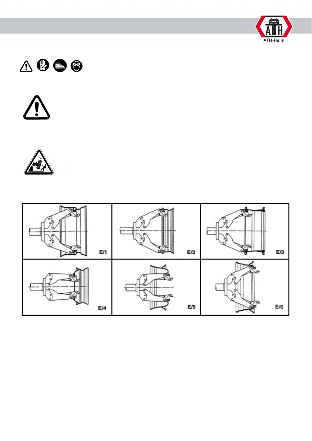
1.3.4. Clamping the wheel
WARNING!
When tightening the rim, make sure that the clamping jaws are correctly
positioned on the rim to prevent the wheel from falling down.
There are different types of truck rims (Fig. 8 E/1-E6).
Use the four clamping jaws to select the appropriate clamp for the rim.
Place the tyre on the inside of the table for the mounting arm.
Move the table until just before the clamping jaws.
Lower the clamping head to the centre of the rim.
Open the clamping jaws until they are smaller than the diameter of the mounting hole.
Slide the tyre over the clamping jaws and open until the tyre is secure.
Check that the rims sit correctly in all four jaws and that the tyre turns smoothly, otherwise it is not
possible to assemble.

® Copyright ATH-Heinl GmbH & Co. KG, 2019, All rights reserved / Misprints and technical changes reserved / As of: 2019-03
Manufacturer ATH-Heinl GmbH & CO.KG
- 8 -
WARNING!
Note that the most secure tension is always at the inner hole.
WARNING!
Never leave the work area while the wheel is still raised or tensioned.
Clamping the wheel
In principle, the guidelines of the German Rubber Industry Trade Association
(Wirtschaftsverband der deutschen Kautschukindustrie) should be observed when
removing tyres.
Handling heavy loads:
- Loads up to 35 kg may be handled by one person, no special handling aids are required
(see also EN 1005);
- Loads between 35 and 70 kg should be handled by two persons (also check the spatial
requirements and instructions) or using the transport / lifting aids provided;
- Loads over 70 kg require a handling or lifting system.
WARNING!
When tightening the rim, make sure that the clamping jaws are correctly
positioned on the rim to prevent the wheel from falling down.
There are different types of truck rims (Fig. 8 E/1-E6).
Use the four clamping jaws to select the appropriate clamp for the rim.

® Copyright ATH-Heinl GmbH & Co. KG, 2019, All rights reserved / Misprints and technical changes reserved / As of: 2019-03
Manufacturer ATH-Heinl GmbH & CO.KG
- 9 -
Move the assembly tower all the way up.
Place the wheel in front of the machine’s clamping jaws and clamp
by operating the clamping lever.
In the case of aluminium rims, please use the enclosed
clamping ring
The wheel can then be brought into a 90° position by operating the
lever for swivelling.
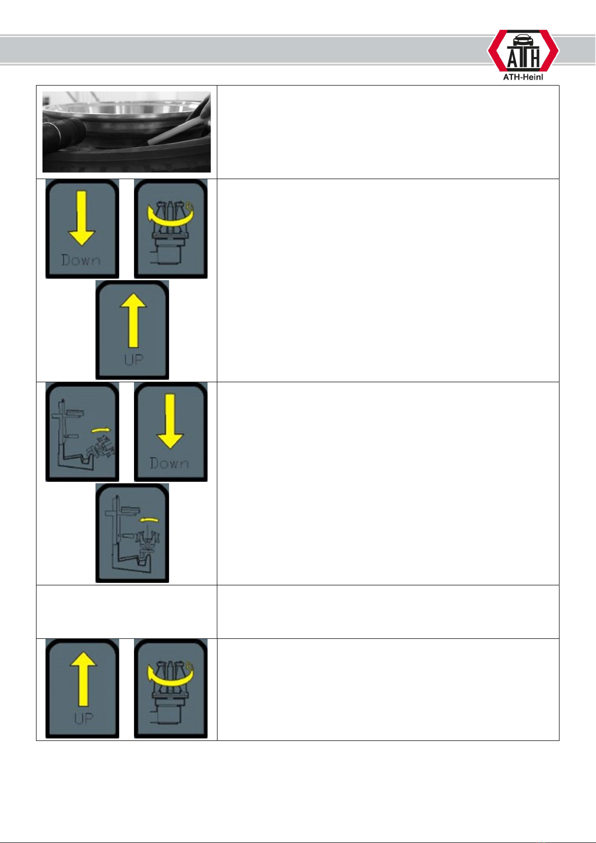
Tyre bead breaker
Preparation
Check the following points before using the device:
- Check whether the power supply is connected properly.
Unscrew the valve insert on the wheel valve and let out all the air.
® Copyright ATH-Heinl GmbH & Co. KG, 2019, All rights reserved / Misprints and technical changes reserved / As of: 2019-03
Manufacturer ATH-Heinl GmbH & CO.KG
- 10 -
First, the tyre bead must be completely pressed off from both sides
of the rim with the bead breaker roller. During this process, the
mounting paste is applied to the rim and the tyre bead.
Start with the upper bead.
Place the bead breaker roller on the outside of the tyre. In order to
complete the assembly without any damage, the roller must be
positioned around 1 cm from the edge of the rim flange.
>
>
Operate the lever for lowering the assembly tower until the tyre is
released from the rim.
Begin the rotation process to release the entire tyre from the rim.
Operate the lever for lifting the assembly tower to release the
pressure from the tyre and allow for swivelling.
>
>
Swivel the wheel forward and lower the assembly tower until the
bead breaker roller is under the wheel. The wheel can then be
swivelled back towards the tower in order to press off the lower
bead.
Press off the lower tyre bead.
Place the bead breaker roller on the outside of the tyre. In order to
complete the assembly without any damage, the roller must be
positioned around 1 cm from the edge of the rim flange.
>
Operate the lever for lifting the assembly tower until the tyre is
released from the rim.
Begin the rotation process to release the entire tyre from the rim.
Then continue with the removal procedure.
Indice
Altri manuali ATH Smontagomme


