Atlantic 36835817 Manuale utente

PART NO: 36835817
MIN: 2.95 in./75 MM
MM
57/.ni
59.2:NIM
MAX: 23.60 in./600 MM
MAX: 15.75 in./400 MM
+0
O
O
-20
For factory use only
Scan this QR code
w i t h y o u r s m a r t
phone to see a helpful
i n s t a l l a t i o n v i d e o
IMPORANT SAFETY INFORMATION. PLEASE
Congratulations on your latest Atlantic purchase. Follow these simple instructions and you’ll
have your TV mounted in no time.
This kit fits most TVs 32 in. - 60 in. (81.28 cm - 152.4 cm), up to 132 lbs (60 kg).
Keep this Instruction Manual for furture reference.
Keep your original proof of purchase (store receipt).
Assembly video is available at www.atlantic-inc.com
www.atlantic-inc.com
If you have any questions and/or wish to order
parts, please call us toll free at 800-747-2660, or
email ‘[email protected]’
?
1
Before Proceeding any further please make sure you ensure your kit has the
following items.
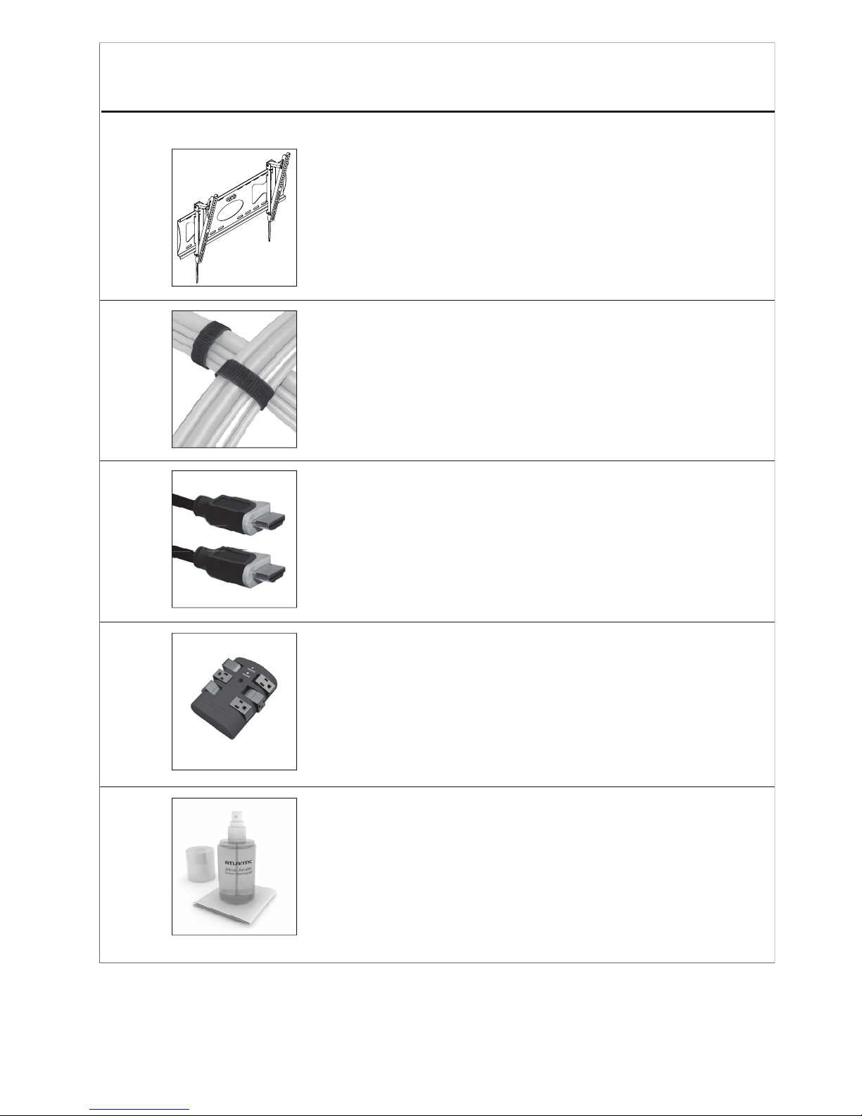
1 x Low Profile Tilting Mount with Built-In Level
2 x 8.66 in. (220 mm) Velcro Cable Ties
2 x 9 ft. HDMI™3D+Ethernet with 1-color braided cables
1 x Wall Tap Surge Protector with 6 pivoting outlets
1 x Cleaning Spray Bottle (6.76oz. (200 ml)) with
1 x 7.87 sq. in. (20 x 20 sq. cm.) Microfiber Cloth
4
F
2
M8X16
M6X12
M5X12
M4X12
M8X40
M6X35
M5X30
M4X30
4
4
4
4
4
4
4
4
M4/M5 washer
M6/M8 washer
M8/M6 spacer
M4/M5 spacer
4
4
4
4
MM
MM
MM
MM
MM
MM
MM
MM
G
H
I
J
K
L
M
N
O
P
Q
R
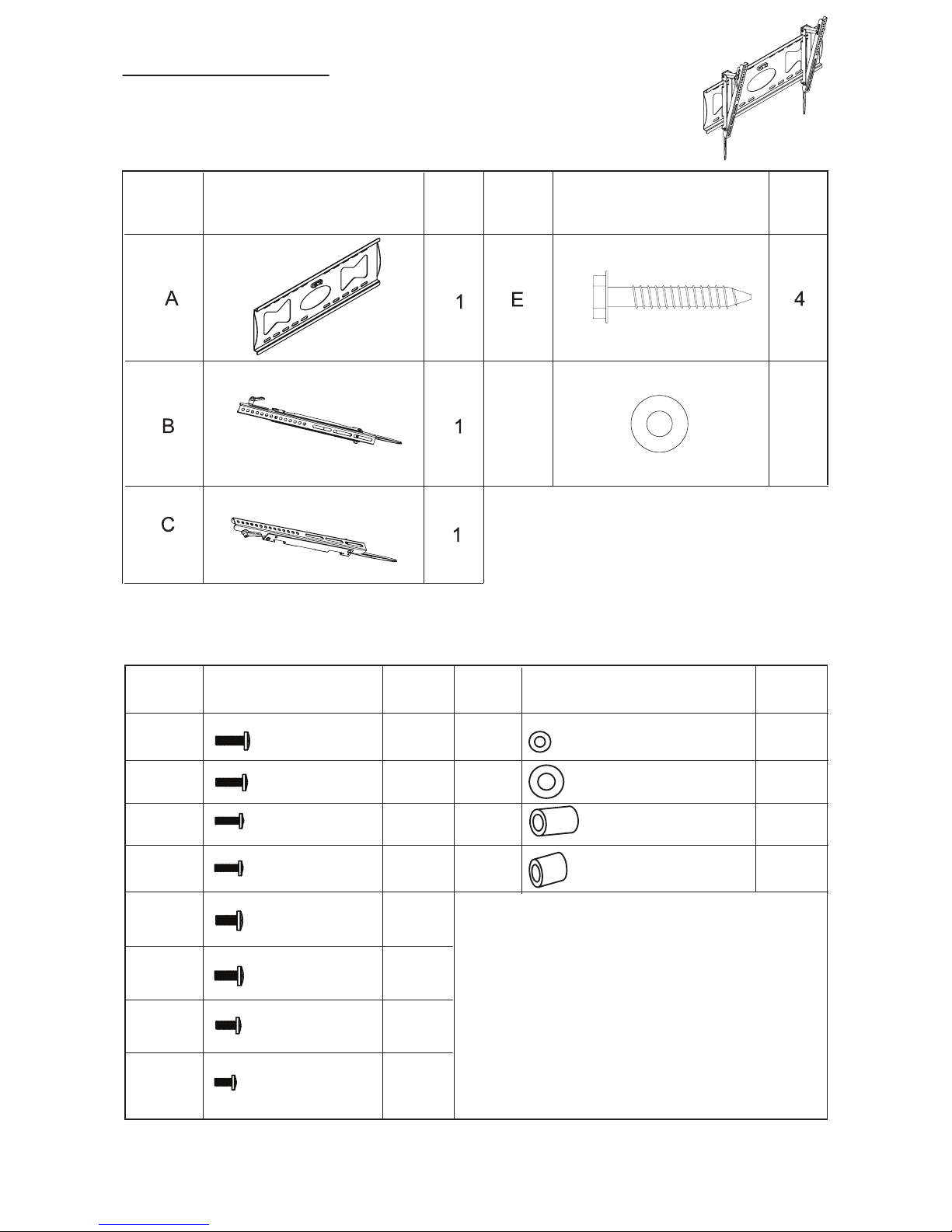
TV Wall Mount
Parts List
Hardware List
Part #
#traP#traP
Part #
metImetI
ItemItem
.ytQ.ytQ
Qty.

3
TV Wall Mount
1/4”or 7 mm
Safety Glasses
Lag Bolt Drill
Bit ¼ in or 7 mm
Drill
Hammer
Philips
Screwdriver
14 mm Wrench
(or 14 mm
socket wrench)
Stud Finder
Tools Needed (not included)

4
2. Never let children climb on product or play with product.
3. Do not sit or stand on product.
4. Do not fasten a TV that is heavier than the recommended load rating to the mount.
1. Improper installation may cause property damage and or personal injury, so the
installation must be done by two qualified contractors. The manufacturer is not
liable for damage or injury cause by incorrect mounting, assembly or use.
5. The size and weight of your TV must not exceed 31.5in. - 60in. diagonally or
132lbs. The wall must be capable of supporting five times the weight of TV plus mount.
.
6. The mount allows the TV to tilt -20°, Maximum extension: 23.6in/600mm,
Minimum extension: 2.95in./75mm.
7. Improper handling can result in cuts and lacerations.
8. Pictures for reference only, subject to our available products.
TV Wall Mount
1. This TV mount is designed for use on a vertical wall that is constructed with wood studs.
2. Become familiar with the instructions and all parts.
3. Make sure that all parts are in the box and in good condition.
4. Assemble the product on the open flat carton or a rug to protect the product and
your floor.
5. Some heavy products need a second person to assist in the assembly. Do not install on
sloping surface.
Assembly Tips:

5
TV Wall Mount
Step 1 Attaching Wall Plate (A)
Using a stud finder, locate center of wood studs in your wall, then hold wall plate (A)
against wall at your desired location. Next, use a pen or pencil to mark the location of where
the 4 mounting screws (E) will go into wall. Before marking, ensure that wall plate
is level using bubble level (already attached to mount.)
Pre-drill the marked 4 holes using 1/4in. (7mm) drill bit. Using a 14mm wrench, fasten wall
plate (A) to wall with screws (E) and washers (F). DO NOT MOUNT INTO DRYWALL.
MUST BE BOLTED TO STUDS.
See Figure 1
This mount is designed to be mounted into wood studs.
Included hardware is not designed to be used in hollow walls, cinder block, red brick, or
metal studs. Should you want to mount your TV mount into any surface other than wood
studs, Atlantic recommends that you seek the assistance of a professional installer.
16 in./406 mm
1erugiF
E(x4)
F(x4)
A
In case the included hardware
is too long, use the spacers.

6
TV Wall Mount
Carefully lay your TV down on rug or flat carton, then attach left bracket (B) and right
bracket (C) to back of TV, then fasten them using hardware included.
(Note - spacers are included in case screws provided are too long for screw holes) See
page 2 for list of spacers included.
TAKE EXTRA CARE AND ATTENTION WHEN YOU FASTEN TWO TV BRACKETS TO THE
Assembly Tip: When attaching the brackets, hand tighten the screws until the brackets are
attached, alighned and tighten snugly.
TV PANEL IN STEP 2. MAKE SURE THE APPROPRIATE MOUNT HARDWARE
IS BEING USED.
Select correct mounting hardware according to the screw hole size of your TV, you may
need spacers on some TV models.
Carefully lay your TV on its face on a non-abrasive surface, making sure to lay padding
underneath it so as not to damage the screen.
Place left mount and right mount in the appropriate position, making sure CENTERED
on the back of TV and level with eachother.
1.
2.
3.
Step 2 Installation of Supports

7
Figure 3
Figure 5
Figure 4
Figure 6
Attention
Down
Handle
.
Hang TV to wall plate as shown in Figure 3.1.
Pull Down to Remove Bracket
Push TV unit lightly to lock it with wall plate, see Figure 4.
2.
To adjust angle of your TV first loosen both adjustment handles, then angle your TV to
your desired poisition. When TV is at desired angle then you can retighten both adjustment
handles. See Figure 5.
3.
If you want to remove TV from bracket at a later time, pull down on both straps to release the
locking mechanism, see Figure 6.
4.
TV Wall Mount
Step 3 Installation of TV to Wall Bracket

8
Surge Protector
Operation Instructions:
Electrical Rating: 15A, 120 VAC, 60Hz, 1800 Watts
Surge Lines Protected: 3-Line (L-N, L-G, N-G)
UL Clamping Voltage: L-N 400V, L-G 400V, N-G 400V
Surge Energy Joule Rating: 2160 Joules
Maximum Spike Current: 144,000 Amps (3 Line Total)
Response Time: < 1 Nanosecond
Max. Spike Voltage: 6KV
Attenuation: Up to 40dB
UL Listed to U.S
Standards: UL 1449, UL 498A
Frequecy: 150KHz~100MHz
EMI/RFI Noise Filter:
Technical Specification:
OPERATION INSTRUCTIONS
Plug Wall tap into Wall Receptacle
Connect electrical devices to the outlets
9
Surge Protector
Information/Functions:
This wall tap surge protector is designed to protect your electronic equipment from AC
power surges up to a certain level. It’s not a lightning arrestor, so it won’t afford protection
while lightning strikes to nearby power lines, house, and/or service entrance antenna’s.
New X3 MOV (Metal Oxide Varistor) Technology:
New designed component with improved material and surge functions absorb surges.
Provides common and normal mode protection from high energy spikes.
Safety Shutdown Technology:
Uses thermal fuses to power off your system, which protects against fire and other damage
in the event of an extreme, extended over-voltage or when surge protection expires.
High-Frequency Capacitor:
Reduces noise interference.
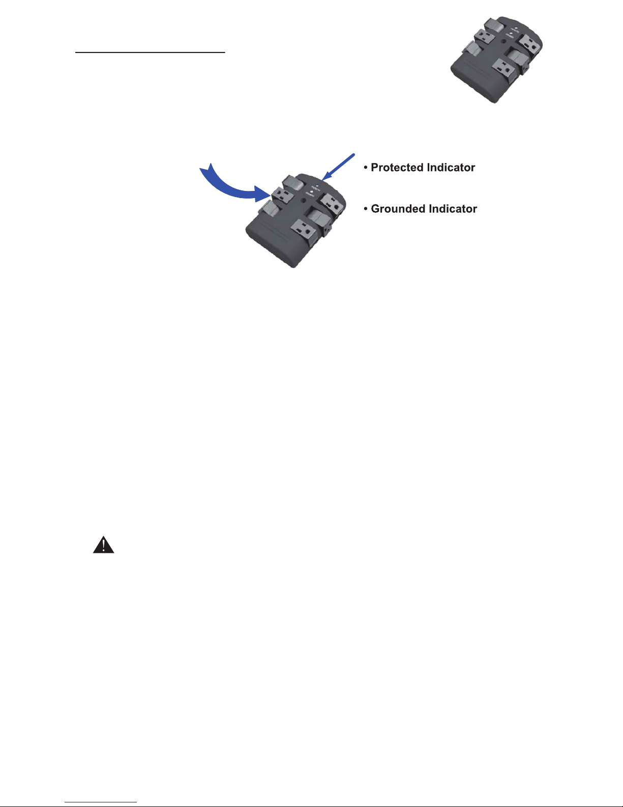
Surge Protected Outlets with 90° Rotating Design:
Can be rotated to a different direction for easy usage with 3line surge protection
Each outlet pivots
90° (degrees) for
your convenience.
Grounded and Surge Protection LED
indicators -
- Green light
indicates your Surge Protection is
working properly.
- Green light
indicates your electrical wiring is
properly grounded.
Do not plug the included surge protector into a power outlet that is different from the specs
called out. If you don’t know or are not sure about the type of electrical power that is sup-
plied to your home, please consult your local power company or a professional electrician.
Use indoor and in dry locations. Not for use with aquariums and other water-related prod-
ucts. This surge protector must be plugged directly into the power source and must not be
‘daisy chained’ together in serial fashion with other power strips, UPS, other surge protec-
tors or extension chords. Risk of fire: Do not exceed electrical rating.
Don’t force your surge protector’s plug into an outlet that isn’t designed to accept a three-
wire grounded-type AC plug (a three-pring plug). This plug is designed to be inserted into a
grounded-type outlet only. If this plug doesn’t fit directly inside your outlet, do not attempt to
force it in. Never attempt to take apart the plug in any way (or alter the power chord). Don’t
attempt to defeat the grounding feature by using a 3-to-2 prong adapter. If you have ques-
tions about grounding, consult your local power company or a qualified electrician.
Caution:
Indice
Altri manuali Atlantic Supporto TV


