Beijer Electronics JetCon 1701GP-U Manuale utente

1
JetCon 1701GP-U
Industrial Gigabit PoE Injector
User’s Manual
Version: 1.1
Date: Nov. 2019

2
Declaration of CE
This product has passed the CE certification for environmental
specifications. Test conditions for passing included the equipment being
operated within an industrial enclosure. In order to protect the product from
being damaged by ESD (Electrostatic Discharge) and EMI leakage, we
strongly recommend the use of CE-compliant industrial enclosure products.
Federal Communications Commission (FCC) Statement
This equipment has been tested and found to comply with the limits for a
Class A digital device, pursuant to Part 15 of the FCC Rules. These limits
are designed to provide reasonable protection against harmful interference
when the equipment is operated in a commercial environment. This
equipment generates, uses, and can radiate radio frequency energy and, if
not installed and used in accordance with the instruction manual, may
cause harmful interference to radio communications. Operation of this
equipment in a residential area is likely to cause harmful interference in
which case the user will be required to correct the interference at his
expense.
The user is cautioned that changes and modifications made to the
equipment without approval of the manufacturer could void the user's
authority to operate this equipment

3
Index
Index.................................................................................................................................. 4
1.
Introduction ................................................................................................................ 1
1-1. Features ............................................................................................................... 2
1-2. Package Checklist................................................................................................ 2
2.
Hardware Description ................................................................................................ 3
2-1. Dimensions........................................................................................................... 3
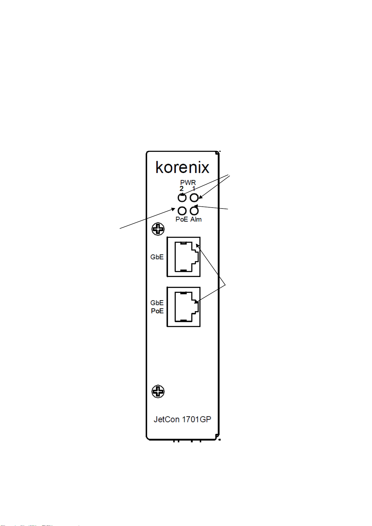
2-2. Front Panel........................................................................................................... 4
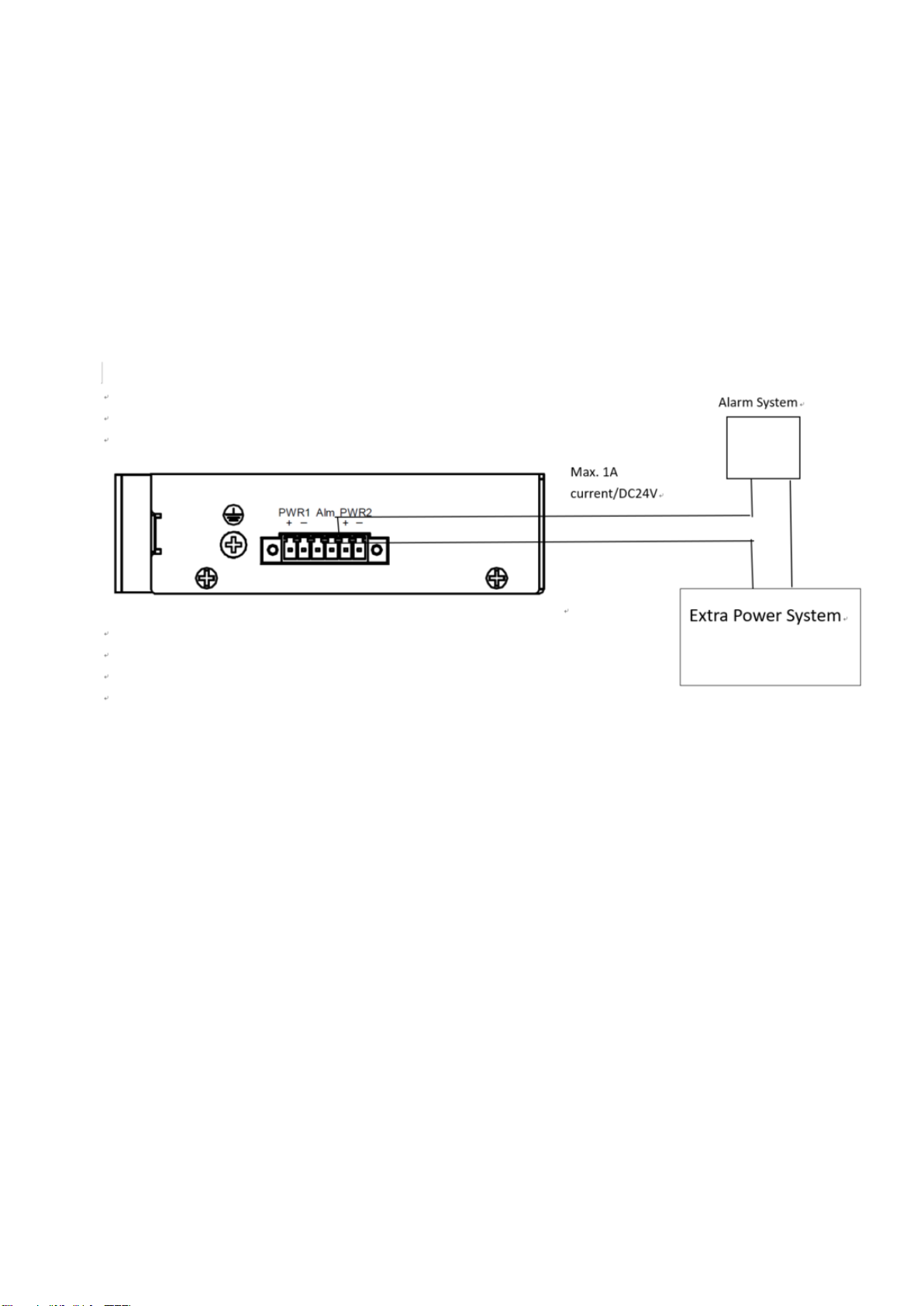
2-3. Bottom View......................................................................................................... 5
2-4. Wiring the DC Power Inputs................................................................................. 6
2-5. Connect the Dry Relay Output............................................................................. 7
2-6. LED Indicators...................................................................................................... 7
2-7. Ports..................................................................................................................... 8
3.
Mounting Installation................................................................................................ 10
3-1. DIN-Rail Mounting.............................................................................................. 10
4.
System Configuration...............................................................................................11
4-1. Quality of Service...............................................................................................11
4-2. Packet Filtering...................................................................................................13
4-3. Link Loss Forwarding (L.L.F.) ............................................................................13
4-4. Event Alarm Relay Configuration.......................................................................14
5.
System Installation...................................................................................................16
5-1. Installation and Testing ......................................................................................16
6.
Troubles shooting .................................................................................................... 19

4
1. Introduction
This document describes the method of how to use the Korenix JetCon
1701GP-U Industrial Gigabit PoE injector, includes installation the
specifications that it has. Following this user manual, you can get fully
imagination about JetCon 1701GP-U and all information to help you
construct the network infrastructure. The following are brief introduction of
JetCon 1701GP-U.
Real Industrial Gigabit Ethernet Media Converter
The JetCon 1701GP-U industrial Gigabit PoE injector equipped a rugged
metal case with thirty-one grade ingress protection to against damaged
solid objects or dust; With the excellent characteristics of heat dissipation,
JetCon 1701GP-U has better survive ability than ordinary Gigabit PoE
injector which is enclosure by steel metal with various of heat dissipation
holes. Not only single power input, the functionality of real time redundant
power backup results in a real Industrial Gigabit PoE Injector with a non-
stop transmission.
Activate Fault Alarm
The JetCon 1701GP-U provides an alarm relay to trigger out a real alarm
signal for power event. The alarm mechanism can be triggered by an
external alarm equipment to inform maintenance I.T. engineers. It makes a
result of maintenance time saving.

5
1-1. Features
Two 10/100/1000Base-T RJ-45
IEEE802.3af/ IEEE802.3at/IEEE 802.3bt compliance
Power redundancy
Rigid IP-31 grade metal case
-40~75℃Wide Operating Temperature
1-2. Package Checklist
JetCon 1701GP-U package includes the following items:
JetCon 1701GP-U x1
One DIN-Rail clip (already screwed on the back of JetCon 1701GP-U x1
JetCon 1701GP-U Quick Installation Guide
Contact your sales representative if any item is missing or damaged.1

6
2. Hardware Description
2-1. Dimensions
The dimension of JetCon 1701GP-U is 120 mm(H) x 30 mm (W) x99 mm (D)
(with DIN rail clip)

7
2-2. Front Panel
The Front Panel of the JetCon 1701GP-U Industrial Gigabit PoE
injector is shown in Figure A
Figure A
Power LED
Gigabit RJ-45 for
10/100/1000 Mbps
Alarm Relay Indicator
LED for PoE

8
2-3. Bottom View
The bottom side of the JetCon 1701GP-U includes one 6-pin removable
terminal block connector.
The power range of JetCon 1701GP-U is from DC 44~57V with redundancy
and polarity reverse function.
To prevent interference and get better performance, it is strongly
suggest make a well earth grounding by the “Earth Ground Screw”.
Earth Ground
Screw
Terminal Block

9
2-4. Wiring the DC Power Inputs
Follow the steps below to wire JetCon 1701GP-U redundant DC power inputs.
[Note] The suitable electric wire ranges from 12 to 23 AWG.
1.
Insert the positive and negative wires into the V+ and V- contactsrespectively
of the terminal block connector
2.
Tighten the wire-clamp screws to prevent the DC wires from being loosened.
3.
The Power 1 and Power 2 support power redundancy and polarityreverse
protection functions.
4.
It accepts positive or negative power system input, but Power 1 and Power2
have to apply the same mode.

10
2-5. Connect the Dry Relay Output
JetCon 1701GP-U provides one dry relay output for fault power event.
The relay conductor ability is 24W when it connects with a DC 24V power source
and maximum current is 1A. In the following diagram shows how to make an alarm
circuit.
About the relay function, please refer section 4-4
2-6. LED Indicators
The front panel of JetCon 1701GP-U includes 2 Power LEDs, 1 LED for
Alarm Relay , 1 LED for PoE. Following table gives descriptions of the
function for each LED indicator.
Indice
Altri manuali Beijer Electronics Convertitore multimediale

Beijer Electronics
Beijer Electronics 100-0973 Manuale utente

Beijer Electronics
Beijer Electronics BoX2 extreme Manuale utente

Beijer Electronics
Beijer Electronics BoX2 pro Manuale utente

Beijer Electronics
Beijer Electronics BoX2 base v2 Foglio di istruzioni

Beijer Electronics
Beijer Electronics BoX2 extreme Manuale utente


