Bewator Bewacard BC610 Manuale utente

Bewacard BC610
Installation and User manual
GB

Copyright © January 1998 Bewator AB, Solna, Sweden.
Material from the BC610 Technical manual may only be copied with the
consent in writing of Bewator. Bewator reserves the right to alter both the
content of the manual and the design of the product.
Document no: BC6100203-GB
Text and layout: WM-data Education AB, Sweden.
Address (Sweden):
Bewator AB
Box 1275
S-171 24 SOLNA, Sweden
Visiting address: Englundavägen 7
Phone: +46 8 627 00 85 (Customer Service)
+46 8 627 00 95 (Reception)
Fax: +46 8 627 00 96
Website: www.bewator.se
E-mail: support@bewator.se
Bewator AB are parts of Bewator Group, which develops and markets a
complete security product range that includes access control, alarm and
time & attendance. Sales, installation and servicing are handled by a national
dealer network.
Actions (such as unauthorised manipulation, copying etc.), must not be taken
with the software contained in the products and systems. Such actions are
regarded as copyright violation and may result in imprisonment or fines and
may likewise lead to an obligation to pay damages and compensation for
using the software.

BC610 Installation and User manual 3
Contents
THIS IS THE BC610......................................................... 4
How does the card reader work?...................................4
Timing security levels......................................................4
Duress...............................................................................5
INSTALLING THE CARD READER ................................ 6
HOW TO SELECT CONNECTING CABLES .................. 7
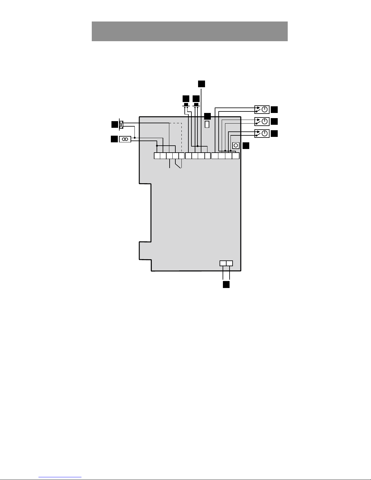
INSTALLATION ............................................................... 8
LAYOUT OF THE KEYPAD........................................... 10
PROGRAMMING ........................................................... 11
Buzzer and LEDs...........................................................11
Set password..................................................................12
Set the card reader to programming mode.................12
Log on a card (with a card)..........................................13
Log on a card (without the card) .................................13
Log on a series of cards.................................................14
Cancel card (with card) ................................................14
Cancel card (without card)...........................................15
Program/change/erase the common code....................15
Change the Door Opening time....................................16
Buzzer on/off..................................................................16
Erase the memory and reset the default settings........17
Change password ..........................................................18
Card parameters ...........................................................19
Door operation on change of toggle enable.................20
PROGRAMMING OVERVIEW....................................... 21
NAME CHART................................................................ 22
DAILY USE..................................................................... 23
Entrance.........................................................................23
The toggle function........................................................23
Choose/change PIN code...............................................24
Duress.............................................................................24
TROUBLESHOOTING................................................... 25
TECHNICAL INFORMATION ........................................ 26

4 BC610 Installation and User manual
This is the BC610
BC610 is a 500 card capacity compact card reader designed
for one door. All programming is done from the keypad.
How does the card reader work?
BC610 can be used in different ways depending on the
security requirements. If no external equipment (time clocks,
push buttons etc.) is connected, card and common code can be
used 24 hours a day. If no common code is programmed the
card reader will only accept cards.
Timing security levels
Using external time clocks, a number of security levels can be
set up. The security level determines what action is required
to open the door. The following security levels exist:
•Unlocked door.
•Common code. A four-digit code (common to all users) is
required to open the door. The common code is
programmed by the person responsible for the card reader.
•Card. The visitor must swipe his card to open the door.
•Card + PIN. The visitor must swipe his card and enter a
personal code to open the door. The card holder can
choose/change his or her personal code on the keypad.
•Toggle function. Used together with current security level,
i.e. Card, Common code or Card + PIN. When the
card/code is swiped/entered the first time the door is
opened and remains unlocked until the card/code is
swiped/entered the next time.
•Card reader disconnected. The card reader is completely
disconnected. Only exit request works.

BC610 Installation and User manual 5
Examples of timing security levels,
During office hours, when there are people in the premises,
the security level may not need to be so high: Unlocked door
or Common code are probably suitable levels.
During lunch time, the level may be raised to Card.
The remaining time, i.e. evenings, nights and weekends, Card
+ PIN is a suitable security level.
The Toggle function can be used in premises where a person
is responsible during certain hours, e.g. a class-room or a
loading bay door.
In a class-room, the teacher can open the door, which remains
open until he or she locks the door. The pupils may come in
and out without having cards or common code.
Duress
BC610 is equipped with a duress output. If a visitor is forced
to open the door under threat, he or she may enter a special
code that activates an alarm.
Note! Duress is only applicable during the Card + PIN
security level.

6 BC610 Installation and User manual
Installing the card reader
Install the card reader at a height of 120–140 cm (from the
floor to the bottom edge of the card reader). To cater for
disabled persons, a suitable height is approximately 95 cm.
To install the card reader:
1Open the card reader with the key supplied. The lock is
located on the underside of the reader.
2Fasten the back plate against the wall, using three screws
according to the illustration below. Seal the screw and
cable holes with sealant if the unit is externally mounted.
3Make sure the back plate is earthed. Use a separate cable
to the earthing point. Make sure the front and back plate
are connected with the internal strap.
4Fit the front and check that the card reader is securely
fastened.

BC610 Installation and User manual 7
How to select connecting cables
It is important to use cables with the correct conductor gauge,
to keep the voltage drop in the cables as low as possible.
•12 volt supplies. A 12 V electric locking device generally
needs at least 11 V to work properly, so the voltage at the
card reader should never be less than 11 V.
•24 volt supplies. A 24 V electric locking device generally
needs at least 21 V to work properly, so the voltage at the
card reader should never be less than 21 V.
The recommended gauge (cross-sectional area) of the
conductor depends on the distance between the power supply
and the card reader, and on the load at the card reader.
The table below is for a Bewacard 610 with an electric
release. The total load is 300 mA at 24 V or 600 mA at 12 V.
24 V Supply 12 V Supply
Cable
length
(metres)
Min conductor Min conductor
area
(mm2)dia
(mm) area
(mm2)dia
(mm)
0-50 0.17 0.46 0.51 0.80
51-100 0.34 0.65 1.02 1.14
101-150 0.51 0.80 1.53 1.40
151-200 0.68 0.93 2.04 1.61
201-250 0.85 1.04 2.55 1.80
251-300 1.02 1.14 3.06 1.95

8 BC610 Installation and User manual
Installation
1 2 3 4 5 6 7
DURESS
0V
CODE
PIN
TOGGLE
READER
INHIBIT
EXIT
BUTTON
LOCK
12-30V
0V
BACK
LIGHT
SW1
15 14
TAMPER
TAMPER
1
2
3 4
5
67
8
9
10
11
8 9 10 11 12 13
+

BC610 Installation and User manual 9
Installation continued
The numbers below refer to the numbers on the wiring diagram.
1Electric locking device. Dashed line shows connection to
locks with fail unlocked operation.
2Power in, terminal block nos. 1 and 2.
3Exit Request button. To operate short terminal nos. 6 and 9.
Optionally, a time-clock can be connected to control a door
that should be permanently open.
4Input for reader inhibit. To operate short terminal nos. 7 and
9. The red LED on the fascia will be lit.
5Duress output. Used for activating an external alarm. Use an
E7 relay. Connect between terminal nos. 8 and + (1).
6Remove the jumper if back lighting is not required.
7Control input for Common code. Terminal nos. 10 and 13
open: Common code enabled. Terminal nos. 10 and 13 linked:
Common code disabled.
8Control input of Card and Card + PIN security levels.
Terminal nos. 11 and 13 open: Card. Terminal nos. 11 and 13
linked: Card + PIN.
9Control input for Toggle function. Link terminal nos. 12 and
13 to activate the toggle function.
10 The SW1 push button. Used to erase the memory and to set a
new password.
11 Tamper switch. Normally closed when the housing is closed.

10 BC610 Installation and User manual
Layout of the keypad
Diagram of the LEDs and push-buttons on the BC610 keypad.
123
456
789
A0B
All LEDs are flashing in programming mode. The LEDs also
have other indications explained in full later.
Red LED.
Indicates errors. E.g.
cancellation of card
following 3 incorrect
PIN codes.
Yellow LED.
Indicates keypresses. Lit when PIN
code should be entered.
Green LED.
Lit when the door is unlocked.
E.g. Accepted card transaction
A.
Initiates program-
ming sequence,
e.g A01 to log on
cards. Also used
when choosing
PIN code
(see page 24).
B.
Press B + the 6-digit password
whenever you want to program
BC610. Press B to leave
programming mode.
Indice
Altri manuali Bewator Sistema di interfono


