Bin Master CNCR-220 Manuale utente
CNCR-210/220 • Two-wire 4
-
20 1
Operating Instructions
Radar sensor for continuous level measurement
CNCR-210
Two-wire 4
-
20 mA
CNCR-220
Two-wire 4
-
20 mA/HART
Document ID: 925-0395 Rev C

CNCR-210/220 • Two-wire 4
-
20 2
Contents
1 About this document ............................................................................................................. 3
2 For your safety ....................................................................................................................... 3
2.1 Authorized personnel ....................................................................................................... 3
2.2 Appropriate use................................................................................................................ 3
2.3 Warning about incorrect use ............................................................................................ 4
3 Product description ............................................................................................................... 4
3.1Conguration.................................................................................................................... 4
3.2 Principle of operation ....................................................................................................... 5
3.3 Adjustment ....................................................................................................................... 5
4 Mounting................................................................................................................................. 6
4.1 General instructions ......................................................................................................... 6
4.2 Mounting versions............................................................................................................ 6
5 Connecting to power supply................................................................................................. 9
5.1 Preparing the connection ................................................................................................. 9
5.2 Connecting..................................................................................................................... 10
5.3 Wiring plan ..................................................................................................................... 11
6 Setup with smartphone/tablet (Bluetooth) ........................................................................ 11
6.1 Preparations................................................................................................................... 11
6.2 Connecting..................................................................................................................... 12
6.3 Parameter adjustment.................................................................................................... 13
7 Menu overview ..................................................................................................................... 14
8 Diagnostics and servicing .................................................................................................. 15
8.1 Maintenance .................................................................................................................. 15
8.2 Status messages ........................................................................................................... 15
9 Removal ................................................................................................................................ 17
10 Certicates and approvals .................................................................................................. 17
10.1 Radio licenses.............................................................................................................. 17
11 Supplement .......................................................................................................................... 18
11.1 Technical data .............................................................................................................. 18
11.2 Dimensions................................................................................................................... 20
CNCR-210/220 • Two-wire 4
-
20 3
Information, note, tip: This symbol indicates helpful additional
information and tips.
Note: This symbol indicates notes to prevent failures, malfunctions,
damage to devices or facility.
Caution: Non-observance may result in personal injury.
Warning: Non-observance may result in serious or fatal personal injury.
Danger: Non-observance of the information marked with this symbol
results in serious or fatal personal injury.
Ex applications
This symbol indicates special instructions for Ex applications.
List
The dot set in front indicates a list with no implied sequence.
Sequence of actions
Numbers set in front indicate successive steps in a procedure.
Battery disposal
This symbol indicates special information about the disposal of
batteries and accumulators.
1 About this document
2 For your safety
2.1 Authorized personnel
Alloperationsdescribedinthisdocumentationmustbecarriedoutonlybytrained,qualied
personnel authorized by the plant operator. Required personal protective equipment must always
be worn when working on or with the device.
2.2 Appropriate use
CNCR-210/220 is a sensor for continuous level measurement. Operational reliability is ensured
onlyiftheinstrumentisproperlyusedaccordingtothespecicationsintheoperatinginstructions.

CNCR-210/220 • Two-wire 4
-
20 4
Safety instructions for Ex areas
TakenoteoftheExspecicsafetyinstructionsforExapplications.Theseinstructions
are attached as documents to each instrument with Ex approval and are part of the
operating instructions.
2.3 Warning about incorrect use
Inappropriateorincorrectuseofthisproductcanresultinapplication-specichazards,e.g.vessel
overllbyincorrectmountingoradjustment.Damagetopropertyandpersonsorenvironmental
contamination can result.
3 Product Description
3.1 Conguration
Fig. 1: Components of CNCR-210/220
1 Radar antenna
2 Processtting
3 Process seal
4 Electronics housing
5 Ventilation/pressure compensation
CNCR-210/220 • Two-wire 4
-
20 5
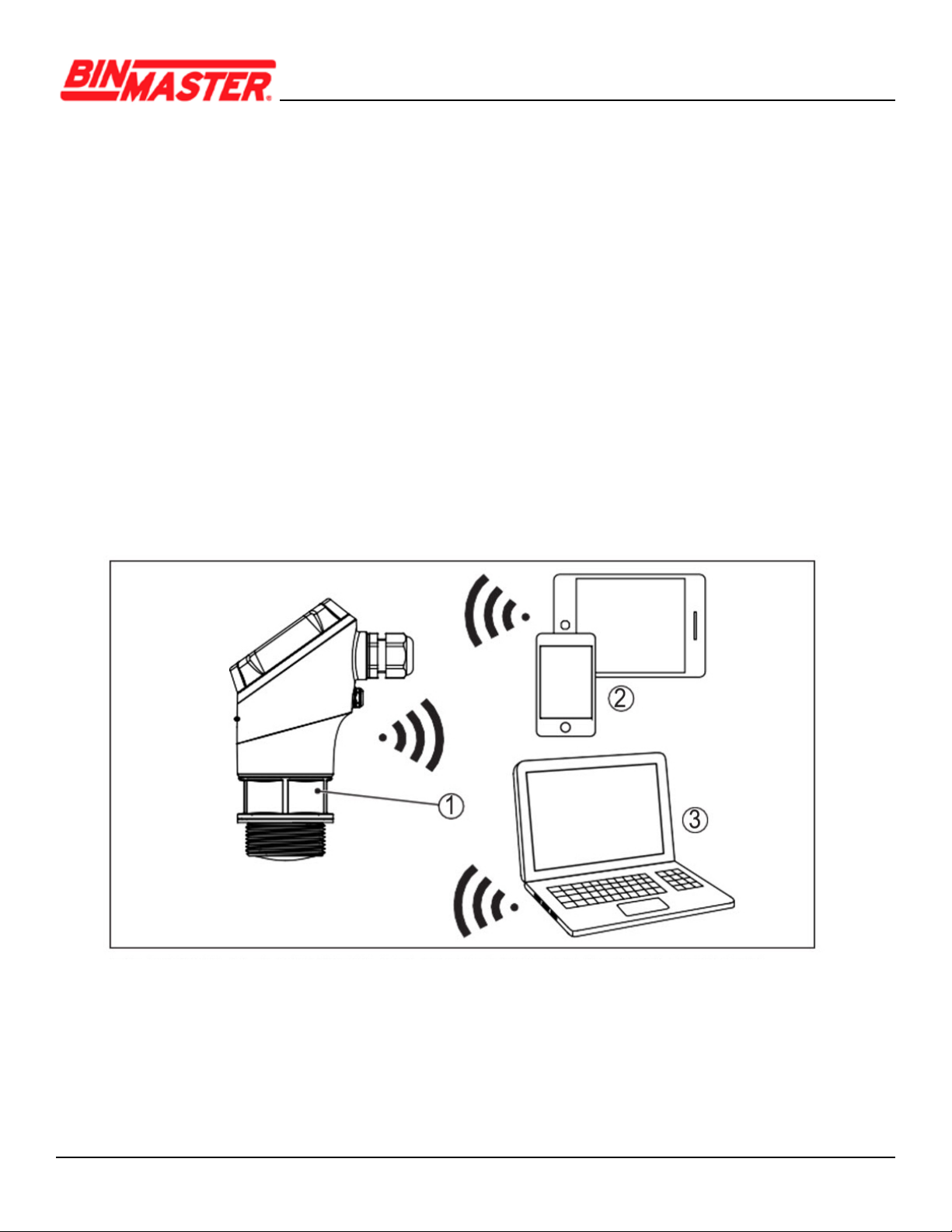
3.3 Adjustment
Devices with integrated Bluetooth module can be adjusted wirelessly via software adjustment tools:
• Smartphone/tablet (iOS or Android operating system)
• PC/notebook with Bluetooth USB adapter (Windows operating system)
Fig. 2: Wireless connection to standard operating devices with integrated Bluetooth LE
1 Sensor
2 Smartphone/Tablet
3 PC/Notebook
3.2 Principle of operation
CNCR-210/220 is a radar sensor for continuous level measurement. It is suitable for liquids and
solids in practically all industries.
The instrument emits a continuous, frequency-modulated radar signal from its antenna. The emit-
tedsignalisreectedbythematerialandreceivedbytheantennaasanechowithamodied
frequency. The frequency change is proportional to the distance to the material.
CNCR-210/220 • Two-wire 4
-
20 6
4.2 Mounting
The radar emits pulses of electromagmetic waves which are polarized. By adjusting the rotation of
the instrument the polarization can be changed to reduce false echoes.
The narrow portion of the radar signal is in the middle of the conduit entry on the instrument. This
should be pointed towards the center of the vessel or any obstacle that may cause any unwanted
reectionstominimizefalseechos,forexample,thesidewallorvesselstructure.
4 Mounting
4.1 General instructions
The instrument is suitable for standard and extended ambient conditions according to DIN/EN/IEC/
ANSI/ISA/UL/CSA 61010-1. It can be used indoors as well as outdoors.
Protect your instrument against moisture ingress through the following measures:
• Use a suitable connection cable
•Tightenthecableglandorplugconnectorrmly
• Face the cable connection or conduit entry downward, never upward
This applies mainly to outdoor installations, in areas where high humidity is expected (e.g. through
cleaning processes) or on cooled or heated vessels.
Fig. 3: Polarization position
Cable / conduit entry
Note:
Whenthehousingisrotated,thedirectionofpolarizationchangesandhencetheinuenceofthefalse
echo on the measured value. Please keep this in mind when mounting or making changes later.

CNCR-210/220 • Two-wire 4
-
20 7
In vessels with cone bottoms, the sensor can be mounted in the center of the vessel to mea-
sure material down to the outlet.
When mounting the sensor, distance it at least 200 mm (7.874 in) from the vessel wall. If the sensor
is installed in the center of dished or round vessel tops, multiple echoes can arise. However, these
can be suppressed by a false signal suppression (see chapter “Setup”).
If you cannot maintain this distance, you should carry out a false signal suppression during initial
setup. This applies particularly if buildup on the vessel wall is expected. If this is the case, we
recommend repeating the false signal suppression later with the additional buildup.
Fig. 5: Mounting the radar sensor with conical bottom
Fig. 4: Mounting the radar sensor on round vessel tops
CNCR-210/220 • Two-wire 4
-
20 8
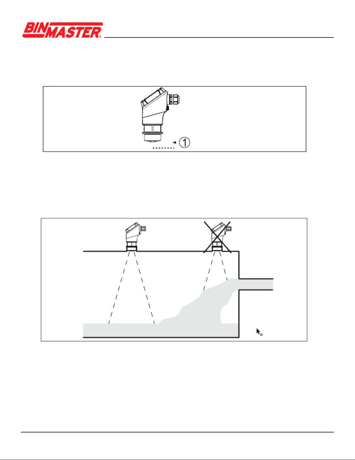
Donotmounttheinstrumentinorabovethellstream.Makesurethatitispointedtowardsthe
materialsurface,notthellstream.
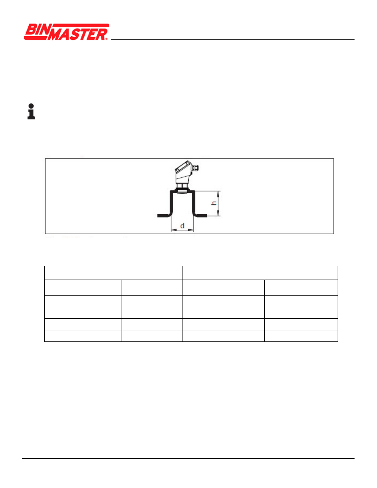
For socket or stand pipe mount, the pipe should be as short as possible and its bottom end
roundedtoreducefalsereectionsfromtheendofthepipe.
When using a threaded coupling, the antenna end should protrude at least 5 mm (0.2 in) out
of the coupling.
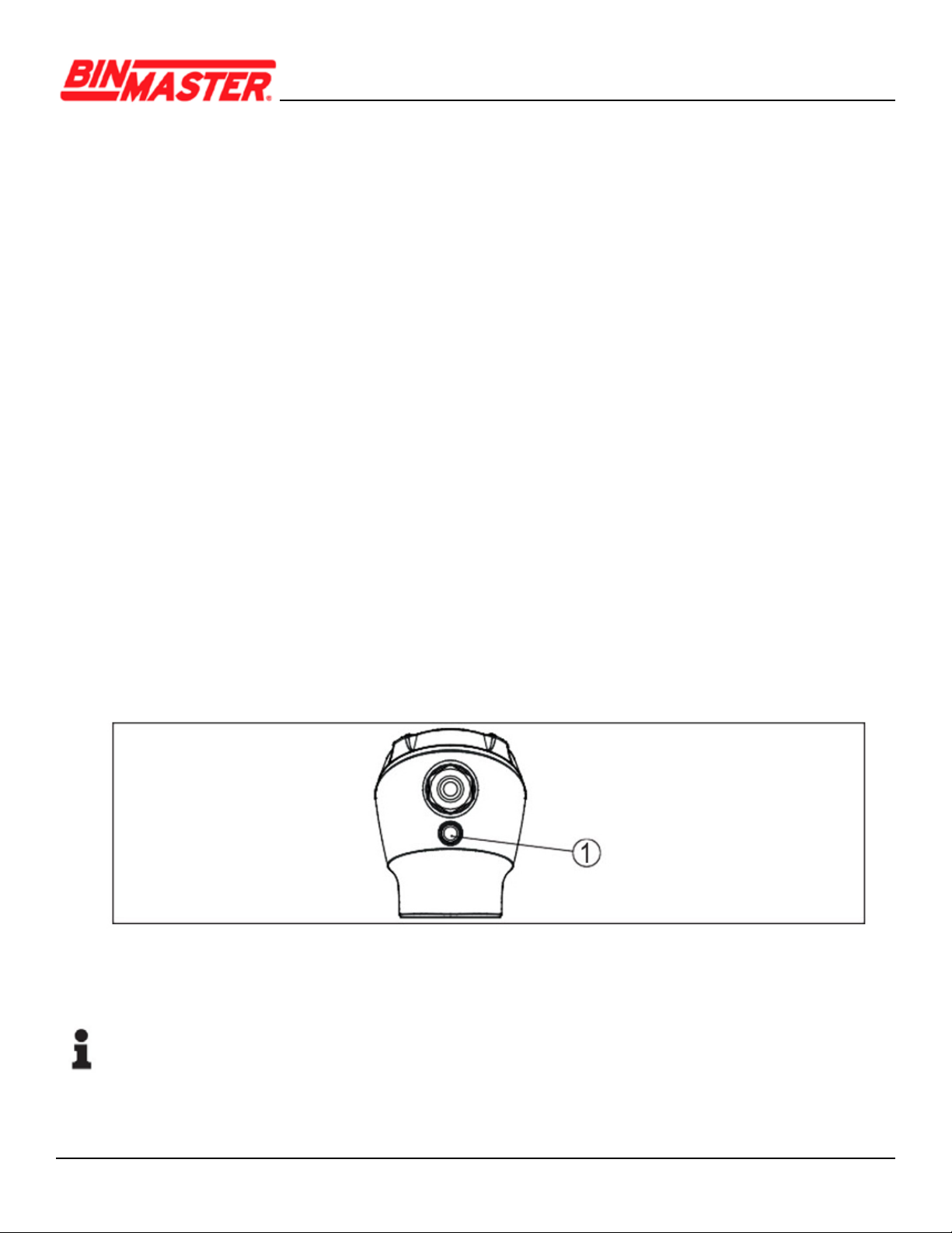
Fig. 6: Reference plane
1 Reference plane
Fig.7:Mountingtheradarsensorwithinowingmaterial
The lower side of the radar antenna is the reference plane for the min./max. adjustment, see
following diagram:
CNCR-210/220 • Two-wire 4
-
20 9
Socket diameter d Socket length h
40 mm 1½” ≤150mm ≤5.9in
50 mm 2” ≤200mm ≤7.9in
80 mm 3” ≤300mm ≤11.8in
100 mm 4” ≤400mm ≤15.8in
150 mm 6” ≤600mm ≤23.6in
Ifthereectivepropertiesofthematerialaregood,youcanmounttheCNCR-210onsockets
or stand pipes longer than the antenna. The pipe end should be smooth, burr-free and the end
rounded.
Note:
When mounting on longer sockets, we recommend carrying out a false signal suppression after
install (see chapter “Parameter adjustment”).
Recommended values for socket or stand pipe lengths and heights are in the following table. The
values come from typical applications.
Fig. 8: Mounting the radar sensor with stand pipes
5 Connecting to power supply
5.1 Preparing the connection
•Electricalconnectionshouldbecompletedbytrained,qualiedpersonnelauthorizedby
the plant operator.
• If overvoltage surges are expected, overvoltage arresters should be installed.
CNCR-210/220 • Two-wire 4
-
20 10
Warning:
Only connect or disconnect in de-energized state.
Note:
Power the instrument via an energy-limited circuit (power max. 100 W) according to IEC 61010-1,
e.g.
• Class 2 power supply unit (acc. to UL1310)
• SELV power supply unit (safety extra-low voltage) with suitable internal or external limitation
of the output current
UseroundcabletoensureeectivesealingofthecableglandtotheappropriateIPratingand
checkthecablediameterversusthecableglandbeforewiringforpropert.
The instrument is connected with standard two-wire cable.
If electromagnetic interference is expected which is above the test values of EN 61326-1 for
industrial areas, shielded cable should be used.
Note:
If the temperatures are too high, the cable insulation can be damaged.
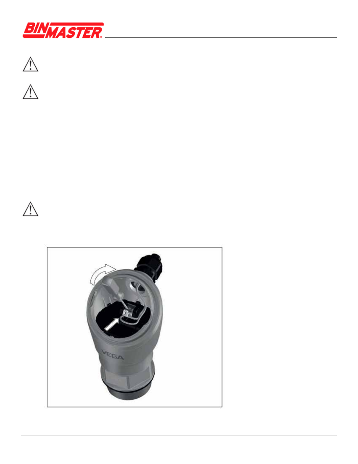
5.2 Connecting
Fig. 9: Connection
Questo manuale è adatto per i seguenti modelli
1
Indice
Altri manuali Bin Master Accessori

Bin Master
Bin Master CNCR-190 Manuale utente

Bin Master
Bin Master NCR-80 Manuale utente

Bin Master
Bin Master NCR-80 Manuale utente

Bin Master
Bin Master NCR-80 Manuale utente

Bin Master
Bin Master NCR-80 Manuale utente

Bin Master
Bin Master SmartBob AO Manuale utente

Bin Master
Bin Master NCR-25 Manuale utente

Bin Master
Bin Master FD-2000 Manuale utente

Bin Master
Bin Master NCR-21 Manuale utente

Bin Master
Bin Master NCR-84 Manuale utente


