Technical Manual
(MTU7391-002-20120402.docx36)
BINDING UNION srl - via Cuorgnè, 21 - 10156 Torino - Italy - Tel. +39 - 011 - 2625414 - Fax +39 - 011 - 2625428 - E-mail binding@binding.it
3
TRANSMITTER 7391 - V / A / ac / dc
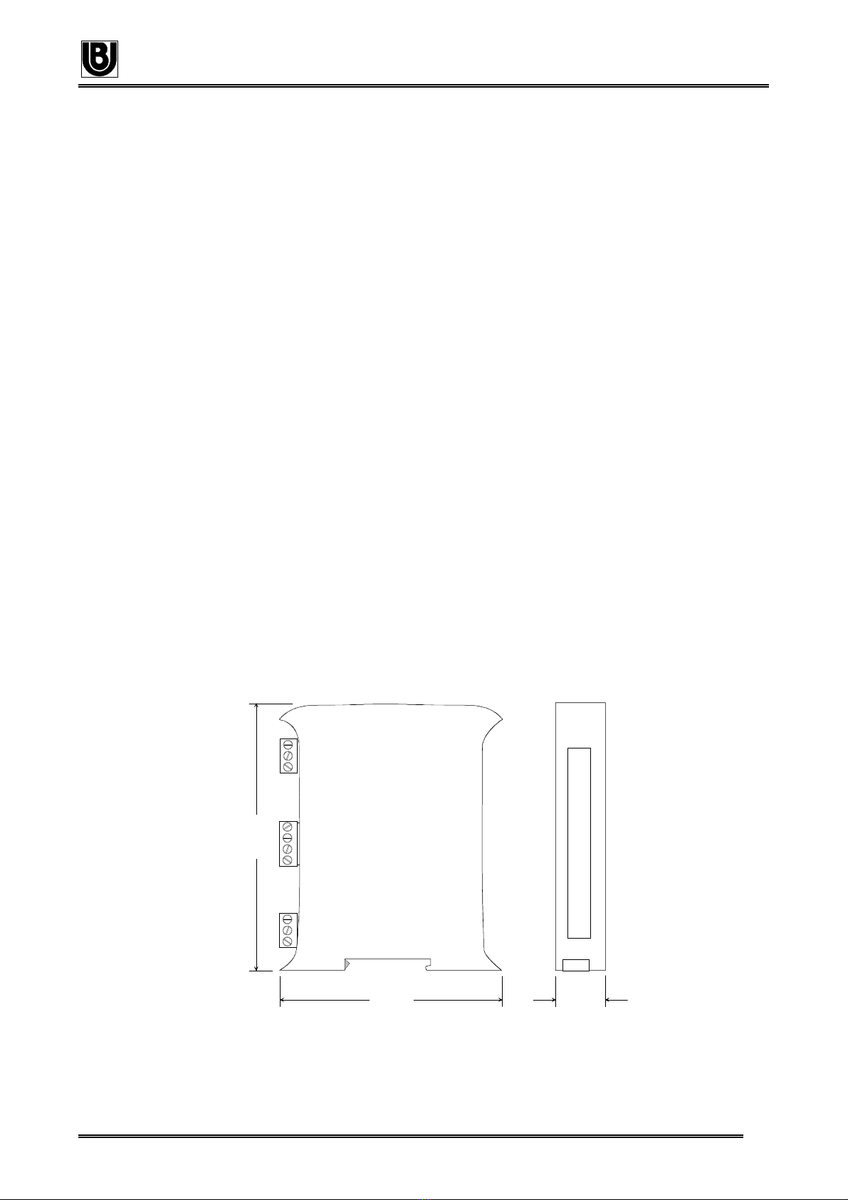
ELECTRICAL CONNECTIONS
S1
1
4
Power
Zero
Span
S2
18
OUTPUT
+
-
+
-
V
SHUNT / 60mV
TA / 5
INPUT POWER SUPPLY
EARTH
(+) L
(-) N
1 2 3 4 5 6 7 8 9 10
INPUT PROGRAMMING
La programmazione deve essere effettuata senza
alimentazione e segnale d’ingresso.
La configurazione, per il tipo di segnale da convertire, si
effettua sul dip-switch S2, raggiungibile dal lato
connessioni tra i morsetti dell’uscita e dell’ingresso. Vedi
tabella sottostante e programmazione facilitata in ultima
pagina. Le scale sono tutte tarate con apparecchiature
di riferimento.
Il modello 739100 permette la completa programmazione
di tutte le scale indicate, il modello 731035 permette la
programmazione delle scale indicate con sfondo bianco, il
modelo 732045 permette la programmazione delle scale
indicate con sfondo colorato.
This programming must be performed when the device is
not powered and without input signal.
Programming of the signal to be converted can be
performed by means of the dip-switch S 2 that is
accessible on the side where the output and input pins
are located.
See table and simplified programming on pag. 4. All
scales are calibrated with certified device.
The model 739100 can be programmed with any of the
scales indicated in the table below. Model 731035
supports the scales indicated with white background.
Model 732045 supports the scales indicated with a
coloured background.
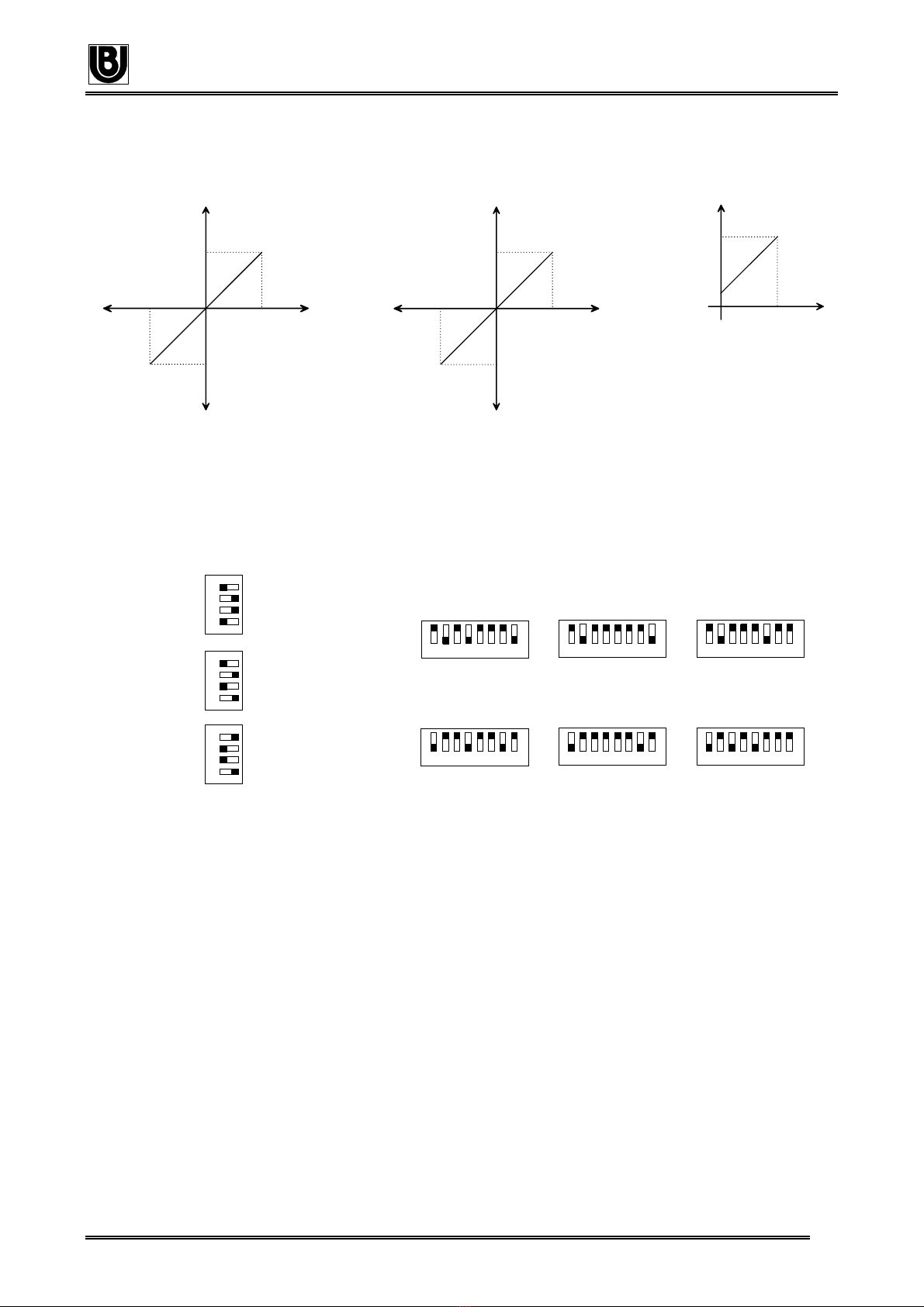
AC ON OFF
DC OFF ON
0...5A ON OFF ON OFF OFF OFF
0...60mV OFF OFF OFF ON OFF OFF
0...300V OFF OFF OFF OFF ON OFF
0...150V OFF ON OFF OFF ON OFF
0...30V OFF OFF OFF OFF OFF ON
0...15V OFF ON OFF OFF OFF ON
OUTPUT PROGRAMMING
La programmazione delle uscite si effettua agendo sul dip-
switch S1, posizionato sul frontale del trasmettitore, sotto i
due trimmer. Vedi tabella sottostante. E’ possibile tuttavia
ritoccare la taratura di zero e di span agendo sui trimmer
frontali, dopo aver atteso 10min. dall’accensione.
Output programming can be performed by means of the
dip-switch S 1, located on the front side, below the two
trimmers See table. However, it is possible to trim the
zero and span by the adjusting front trimmers, after
10min. of warm-up time.
0...10V ON OFF OFF ON
0...20mA ON OFF ON OFF
4...20mA OFF ON ON OFF
I Trasmettitori programmati per segnali in continua e
uscita 0...10V o 0...20mA sono di tipo bipolare, cioè
forniscono un segnale di ±10V o ±20mA proporzionale al
segnale d’ingresso (±15Vcc, ±30Vcc, ±60mV da shunt).
Quando programmati per ingresso in alternata o uscita
4...20mA sono unicamente di tipo unipolare. Vedi funzioni
di trasferimento nella pagina seguente
The transmitters programmed for dc input signals and
0...10V or 0...20mA outputs are bipolar types, that is
provide a signal of
±
10V or
±
20mA proportional to the
input signal of
±
15Vcc,
±
30Vcc,
±
60mV.
When the trasnsmitters are programmed for ac input
signals or 4...20mA output they are unipolar type only.
The following page shows the transfer functions.