BioSmart PV-WTC-EM Manuale utente
BioSmart PV-WTC
Installation Guide
www.biosmart-tech.com

Biosmart PV-WTC Terminal. Installation guide v 2.4|en
2
CONTENTS
CONTENTS
GENERAL PRODUCT INFORMATION .......................................................................................................4
1. SPECIFICATIONS................................................................................................................................4
1.1. Basic specifications ..................................................................................................................................... 5
1.2. Factory settings........................................................................................................................................... 6
1.3. Package contents ........................................................................................................................................ 6
2. USE, TRANSPORTATION AND STORAGE CONDITIONS...............................................................6
3. SAFETY REQUIREMENTS..................................................................................................................6
4. DISPOSAL ...........................................................................................................................................7
5. MANUFACTURER’S GUARANTEE ...................................................................................................7
6. INSPECTION CERTIFICATE................................................................................................................7
7. TERMINAL DESCRIPTION.................................................................................................................8
7.1. Terminal’s front panel description .............................................................................................................. 8
7.2. Description of connection ports .................................................................................................................. 9
7.3. Description of indicators and circuit board jumpers...................................................................................11
8. INSTALLATION.................................................................................................................................11
8.1. Installation notes .......................................................................................................................................11
8.2. Installation procedures ..............................................................................................................................13
8.3. Connecting the terminal’s power supply....................................................................................................15
8.4. Connecting the terminal to an Ethernet network.......................................................................................16
8.5. Connecting an electromechanical lock to the terminal’s circuit board .......................................................17
8.6. Connecting an electromagnetic lock through the BioSmart Zflex Relay Module.........................................18
8.7. Connecting an entry sensor and control buttons........................................................................................19
8.8. Connecting to an external controller through Wiegand .............................................................................21
9. NETWORK PARAMETERS CONFIGURATION.............................................................................. 22
10. ERRORS CHECK............................................................................................................................... 23
Biosmart PV-WTC Terminal. Installation guide v 2.4|en
3
Safety Instructions
Safety Instructions
Safety instructions must be followed in addition to International Standards (ISO/IEC)*, and
other safety regulations.
Caution
Caution indicates a hazard with a low level of risk which, if not avoided, could
result in minor or moderate injury.
Note
Note indicates an important remark, which should be taken into attention.
Caution
General requirements:
Read, follow and retain instructions –All safety and operating instructions must
be read and followed properly before putting the unit into operation.
Do not turn on the power supply until all installation procedures are finished –
this may lead to injury or equipment damage.
Do not disconnect or connect cables while unit is powered on –this may lead
to unit malfunction and software errors.
Do not expose unit to heat or fire –high temperature impact may lead to case
deformation and circuit board damage.
Make sure that all cables and screws are fastened properly - otherwise case
damage or circuit shortcut may happen.
Note
Additional requirements:
Use a clean, dry cloth to remove any dirt or dust from the unit.
*IEC 60204-1: Safety of machinery –Electrical equipment of machines. (Part 1: General
requirements)

Biosmart PV-WTC Terminal. Installation guide v 2.4|en
4
General product information
Dear customers!
Thank you for purchasing our product. With proper installation and use, this
device will bring you many years of reliable service.
General product information
The BioSmart PV-WTC Work and Attendance Terminal is designed for use as part
of the BioSmart biometric access monitoring and control system. The terminal
provides a means to track working hours and attendance by identifying users through
the unique biometric characteristics of subcutaneous palm veins and RFID proximity
cards. It can also be used for access monitoring and control.
Terminal is compatible with BioSmart Studio V5.6.3.269 and above.
Four models of this terminal are available:
- With Em-Marine (EM) card format scanner;
- With Mifare (MF) card format scanner;
- With HID iClass and HID Prox (HD) card format scanner;
- With Legic (LG) card format scanner.
1. SPECIFICATIONS
Designation
Device serial number
BioSmart PV-WTC -EM
BioSmart PV-WTC -MF
BioSmart PV-WTC -HD
BioSmart PV-WTC -LG

Biosmart PV-WTC Terminal. Installation guide v 2.4|en
5
SPECIFICATIONS
1.1. Basic specifications
- Palm vein scanner type
Optical, infrared
- Maximum number of users*
1 000 000
- Maximum numbers of card codes
1 000 000
- Maximum number of palms
300 000
- Maximum number of events
10 000 000
- 1:1000 vein identification time, s
no longer than 2
- False acceptance rate,, % **
0.00008
- Integrated RFID card scanner
Yes
- Card scanning range, mm
up to 100
- Display
TFT 3.5” 320х240
- Keyboard
12 buttons
- BioSmart relay module support
Yes
- PC connection
Ethernet (IEEE 802.3,
10BASE-T, IEEE
802.3u, 100BASE-TX,
1000BASE-TX)
- USB interface
USB2.0 Full Speed
- WEB-interface
Yes
- Wiegand 26-40 bites
Yes
- On-board relay
12 VDC, 1 А
- Number of discrete inputs, pcs
1
- Power supply specifications
12 VDC±15%, 1 A
- POE
IEEE802.3af class 3
- Outer dimensions (L x W x H), mm
220х155х130
- Net weight, g
850
- Gross weight, g
1200
- Operating temperature range, °С
from 0 to plus 50
- Operating relative air humidity, %
up to 90
- Ingress Protection Rating
IP54
- Design
Detachable plastic body
Note: * - Each user can be provided with single card code
** - Calculated value. Depends on user’s templates quality

Biosmart PV-WTC Terminal. Installation guide v 2.4|en
6
USE, TRANSPORTATION AND STORAGE CONDITIONS
1.2. Factory settings
IP address
172.25.110.71
Administrator password
No password
WEB-interface login
root
WEB-interface password
bioroot
1.3. Package contents
Item
Number, pcs
BioSmart PV-WTC Terminal
1
Installation guide
1
Warranty claim
1
Mounting kit (four 6х35 dowels, four
3.5х38 self-tapping screws)
1
2. USE, TRANSPORTATION AND STORAGE CONDITIONS
Abrasive or chemically active materials should not be used to clean the outer
surfaces of the device or the palm vein scanner.
The terminal may be stored in the following environmental conditions:
- ambient air temperature from minus 40 to plus 50°С;
- relative air humidity (without condensation) up to 98%.
Water, dust and other foreign substances should be prevented from entering the
inside of the terminal during transportation and storage. Following storage of the
terminal in low temperature or high humidity conditions, it must be kept in a dry
environment at a temperature of (20±5) °С for no less than 30 minutes before being
turned on.
3. SAFETY REQUIREMENTS
To avoid malfunctions in the terminal, it must be disconnected from its power
source before any work is carried out with its case open.
Only specialists authorized by the manufacturers of this terminal should carry out
the repair and replacement of terminal parts.

Biosmart PV-WTC Terminal. Installation guide v 2.4|en
7
DISPOSAL
4. DISPOSAL
The BioSmart PV-WTC Terminal does not contain materials hazardous to the
health of users or the environment. No special ecological safety measures are
required when disposing of this unit at the end of its operational lifespan.
5. MANUFACTURER’S GUARANTEE
The manufacturer guarantees successful performance and correspondence to the
stated product characteristics on the condition that the consumer complies with the
rules of its use, installation, connection, transportation and storage.
The manufacturer provides a warranty on the BioSmart PV-WTC Terminal for the
period of 36 months from the day of sale indicated in its certificate.
If notes on the date of the product’s sale are absent from the certificate, the
warranty period is calculated from its manufacturing date.
The Manufacturer’s Warranty does not extend to BioSmart PV-WTC terminals
that have broken down due to the Customer failing to comply with its rules of
operation.
6. INSPECTION CERTIFICATE
«BioSmart PV-WTC-_____» terminal, assembly n. _________________ has been
classified as fit for use.
Issue date _______________

Biosmart PV-WTC Terminal. Installation guide v 2.4|en
8
TERMINAL DESCRIPTION
7. TERMINAL DESCRIPTION
7.1. Terminal’s front panel description
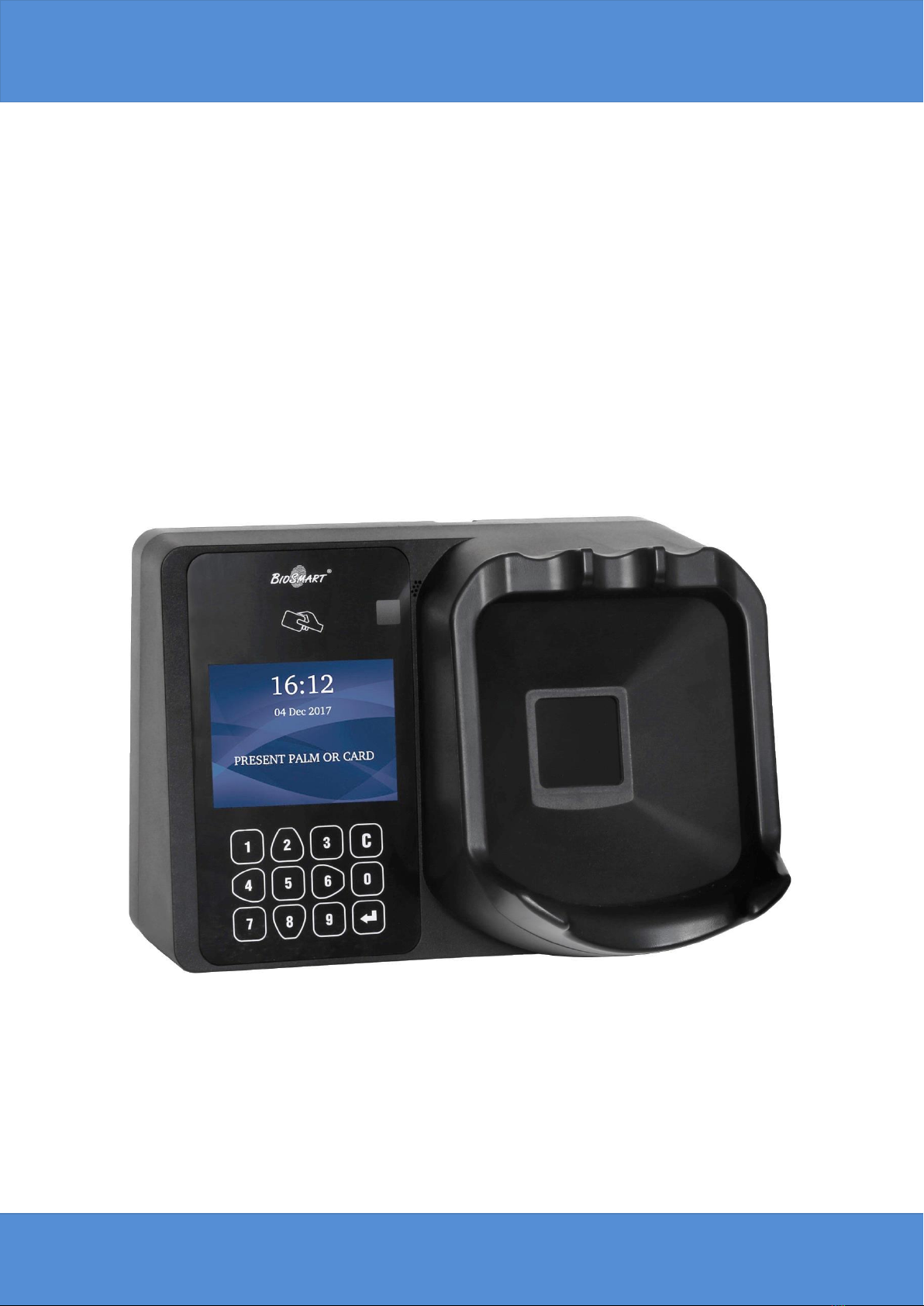
An exterior view of terminal is shown on the figure 1.
Figure 1. Exterior view of the terminal
1. RFID card reader;
2. LCD screen;
3. Keypad;
4. Camera (optional);
5. Palm vein scanner;
The keypad buttons (fig. 2) are used to navigate through the on-screen menu:

Biosmart PV-WTC Terminal. Installation guide v 2.4|en
9
TERMINAL DESCRIPTION
Figure 2. Keypad
2–moves up the list;
6–moves to the right or switches from list to function buttons. Used for page
navigation in the «Employees» menu;
4–moves to the left or switches from function buttons to list. Used for page
navigation in the «Employees» menu;
5–used for selection and confirmation in the «Employees» menu;
8–moves down the list;
–used for selection and confirmation;
–used to return to the previous menu section or delete the last digit entered.
The keypad is also used to enter all numeric settings.
7.2. Description of connection ports
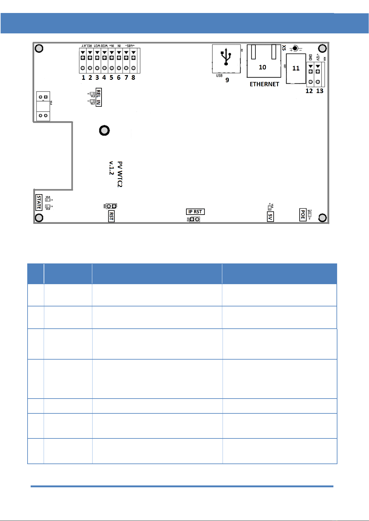
A view of the terminal’s circuit board is shown in fig. 3. The circuit board’s
contacts are described in table 1.
Biosmart PV-WTC Terminal. Installation guide v 2.4|en
10
TERMINAL DESCRIPTION
Figure 3. Exterior view of terminal’s circuit board
Table 1. Circuit board connectors
№
Label
Description
Connection purpose
1
RELAY
1st relay normally-open contact output
(DC 1A, 12V)
Actuator control input
2
RELAY
2nd relay normally-open contact output
(DC 1A, 12V)
Actuator power supply output
3
WO1
Wiegand interface DATA1 output
Wiegand external controller
interface DATA 1 intput
4
WO0
Wiegand interface DATA0 output
Wiegand external controller
interface
DATA0 intput
5
IN+
+12V output for discrete input
Relay control button
6
IN
Discrete input
Door sensor output, relay control
button
7
485-
- interface of RS485 connection with
Zflex
+485 Zflex contact
Questo manuale è adatto per i seguenti modelli
4
Indice
Altri manuali BioSmart Controllori di accesso IP


