Black Box Blackbox-M Manuale utente


Nice Housing, Stoutness & Stability, Advanced and Reliable functions, Perfect &
Valuable. Approval. BLACKBOX-M mobile radio especially designs
for drivers and it pursues company philosophy of innovation and practicality.
NOTE
:KHQSURJUDPPLQJWKHWUDQVFHLYHUUHDGWKHIDFWRU\LQLWLDOGDWD¿UVWO\WKHQUHZULWHWKHIUHTXHQF\DQGVLJQDOLQJHWF
RWKHUZLVHHUURUVPD\RFFXUEHFDXVHRIGLIIHUHQWIUHTXHQF\EDQGHWF
Models Apply To This Manual: BLACKBOX-M Mobile radio
BLACKBOX-M Mobile Radio Applicable Software: BLACKBOXSetup

Thank you for choosing this vehicle transceiver,
always provides high quality products, And this transceiver is no
H[FHSWLRQ$V\RXOHDUQKRZWRXVHWKLVWUDQVFHLYHU\RXZLOO¿QGWKDW
is pursuing "user friendliness". For example, each time you
change the menu no. in Menu mode, you will see a text message on the
GLVSOD\WKDWOHWV\RXNQRZZKDW\RXDUHFRQ¿JXULQJ
Though friendly design for user, this transceiver is technically
complicated and some features may be new to you. Consider this
manual to be a personal tutorial from the designers,allow the manual to
guide you through the learning process now, then act as a reference in
the coming years.
Do not attempt to configure your transceiver while driving,it is
dangerous.
This transceiver is designed for a 13.8V DC power supply. Don't use
a 24V battery to power on the transceiver.
Do not place the transceiver in excessively dusty, humid or wet
areas, nor unstable surfaces.
Please keep it away from interferential
devices (such as TV, generator etc.)
Do not expose the transceiver to long
periods of direct sunlight nor place it close
to heating appliances.
If an abnormal odor or smoke is detected
coming from the transceiver, turn OFF the
power immediately. Contact
or your dealer.
Do not transmit with high output power for extended periods; the
transceiver may overheat.
Please observe the following precautions to prevent fire, personal
injury, or transceiver damage:
Precautions
Please contact the local authorized dealer if you have any questions.We are not responsible for
any typographical errors that may be in this manual. Standard accessories may change withou t
notice, getting your understanding for any inconveniences.
When programming the transceiver, read the factory
initial data firstly, then rewrite the frequency and signaling
etc., otherwise errors may occur because of differen t
frequency band etc..

CONTENTS
1HZDQG,QQRYDWLYH)HDWXUHV..............................................1
Supplied Accessories/Optional Accessories.....................2
Supplied Accessories....................................................................... 2
Optional Accessories .......................................................................2
,QLWLDO,QVWDOODWLRQ ..................................................................3
Mobile Installation ............................................................................ 3
DC Power Cable Connection ...........................................................4
Power Supply Voltage Display ......................................................... 6
Antenna Connection ........................................................................ 6
Accessories Connections................................................................. 7
*HWWLQJ$FTXDLQWHG ..............................................................8
Front panel....................................................................................... 8
Rear panel ....................................................................................... 9
Display .............................................................................................9
Microphone ......................................................................................10
Working Mode(Amateur Transceiver or Professional
Transceiver)
........................................................................11
Basic Operations .................................................................12
Switching the Power On/Off ............................................................12
Adjusting the Volume ......................................................................12
Switch between VFO and Channel mode .......................................12
Adjusting Frequency/Channel Through Selector Knob.................... 12
Receiving .........................................................................................12
Transmitting .....................................................................................12
Transmitting Tone-Pulse .................................................................. 13
Transmitting Optional Signaling ...................................................... 13
Channel Edit .................................................................................... 13
Channel Delete ................................................................................ 13
Shortcut Operations.............................................................14
Squelch Off/Squelch Off Momentary................................................14
Squelch Level Setup ........................................................................14
Frequency/Channel Scan ................................................................ 14
Channel Scan .................................................................................. 14
CTCSS/DCS Encode and Decode Setup ........................................14
CTCSS Scan....................................................................................15
DCS Scan ........................................................................................ 15
High/Mid/Low Power Switch ............................................................15
Compander (Decrease the background noise and enhance audio
clarity ..................................................................................................15
Offset Direction and Offset Frequency Setup ..................................16
Keypad Lockout ............................................................................... 16
Current Voltage Enquiry...................................................................16
Auto-Dialer Setup.............................................................................16
Transmitting Edited DTMF Tones in the Auto-dialer Memory...........17
General Setting.....................................................................18
Frequency Channel Step Setup....................................................... 18
DTMF, DTMF ANI, 2Tone or 5Tone Signaling .................................. 18
Sending 2-Tone Call.........................................................................19
Sending 5-Tone Call.........................................................................19
Sending DTMF call .......................................................................... 19
Signaling Combination Setup...........................................................19

CONTENTS
HIGH/MID/LOW Power Selection ....................................................20
Band-width Selection ....................................................................... 20
TX OFF Setup.................................................................................. 21
Busy Channel Lockout .....................................................................21
Editing Channel Name .....................................................................21
Reverse TX/RX ................................................................................21
Talk Around ......................................................................................22
Voice Compander ...........................................................................22
Scrambler Setup (Encryption).......................................................... 22
Radio's DTMF SELF ID ENQUIRY ................................................. 22
Radio's 5TONE SELF ID ENQUIRY ...............................................23
Voice Prompt.................................................................................... 23
TOT (Time-out timer) .......................................................................23
APO (Auto power off)....................................................................... 23
DTMF Transmitting Time.................................................................. 24
Squelch Level Setup ........................................................................24
Scan Dwell Time Setup....................................................................24
LCD Backlight .................................................................................. 24
Pilot Frequency ................................................................................ 25
Display Mode Setup......................................................................... 25
PIN Setup ........................................................................................25
Address List ....................................................................................26
Factory Default.................................................................................26
Microphone Operation .........................................................27
Function Setup By Microphone Keypad........................................... 27
Squelch Level .................................................................................. 27
Optional Signaling ...........................................................................27
Scan Skip ........................................................................................28
Frequency/Channel Scan ...............................................................28
Busy Channel Lockout .....................................................................28
Reverse TX/RX ................................................................................28
TOT (Time-out timer)........................................................................ 29
CTCSS/DCS Encode and Decode................................................... 29
Talk Around .....................................................................................29
Voice Prompt.................................................................................... 29
HIGH/MID/LOW Power Selection ....................................................29
LCD Backlight .................................................................................30
Long-distance Anti-theft Alarm ..........................................31
Cable Clone ..........................................................................32
3URJUDPPLQJ6RIWZDUH,QVWDOOLQJDQG6WDUWLQJLQZLQGRZV
XP system) ............................................................................33
Maintenance..........................................................................34
Default Setting after Resetting(VHF) ............................................... 34
Default Setting after Resetting(UHF) ...............................................34
Trouble Shooting..............................................................................34
6SHFL¿FDWLRQV .......................................................................35
Attached Chart......................................................................36
50 groups CTCSS Tone Frequency(Hz) ..........................................36
1024 groups DCS Code................................................................... 36

1
1
New and Innovative Features
Mobile Radio has nice housing, stoutness & stability, advanced and reliable functions, perfect & valuable. This amateur mobile radio
especially designs for drivers and it pursues company philosophy of innovation and practicality. More functions as follows:
Display on a large LCD with adjustable brightness, convenient for nighttime use. There are Amateur operation mode and Professional
operation mode for option.
Distribute buttons reasonably, convenient for operation. Adopt superior quality material, better technology and high quality radiator to ensure
stable and durable operation.
SURJUDPPDEOHPHPRUL]HGFKDQQHOVLGHQWL¿HGE\HGLWLQJQDPH
Programming different CTCSS, DCS, 2Tone, 5Tone in per channel, rejecting extra calling from other radios.
Various scan functions including CTCSS/DCS Scan function.
Using 5Tone to send Message, Emergency alarm, Call all, ANI, Remotely kill, Remotely Waken, etc.
$XWRPDWLFFDOOLQJ,GHQWL¿FDWLRQIXQFWLRQE\'70)$1,RU7RQH$1,
Scramble function (Optional).
Compander function for decrease the background noise and enhance audio clarity, it can set compander ON/OFF per channel.
Different band width per channel, 25K for wide band, 20K for middle band ,or 12.5K for narrow band.
Theft alarm provides extra safety.

2
2Supplied Accessories/Optional Accessories
Supplied Accessories
Optional Accessories
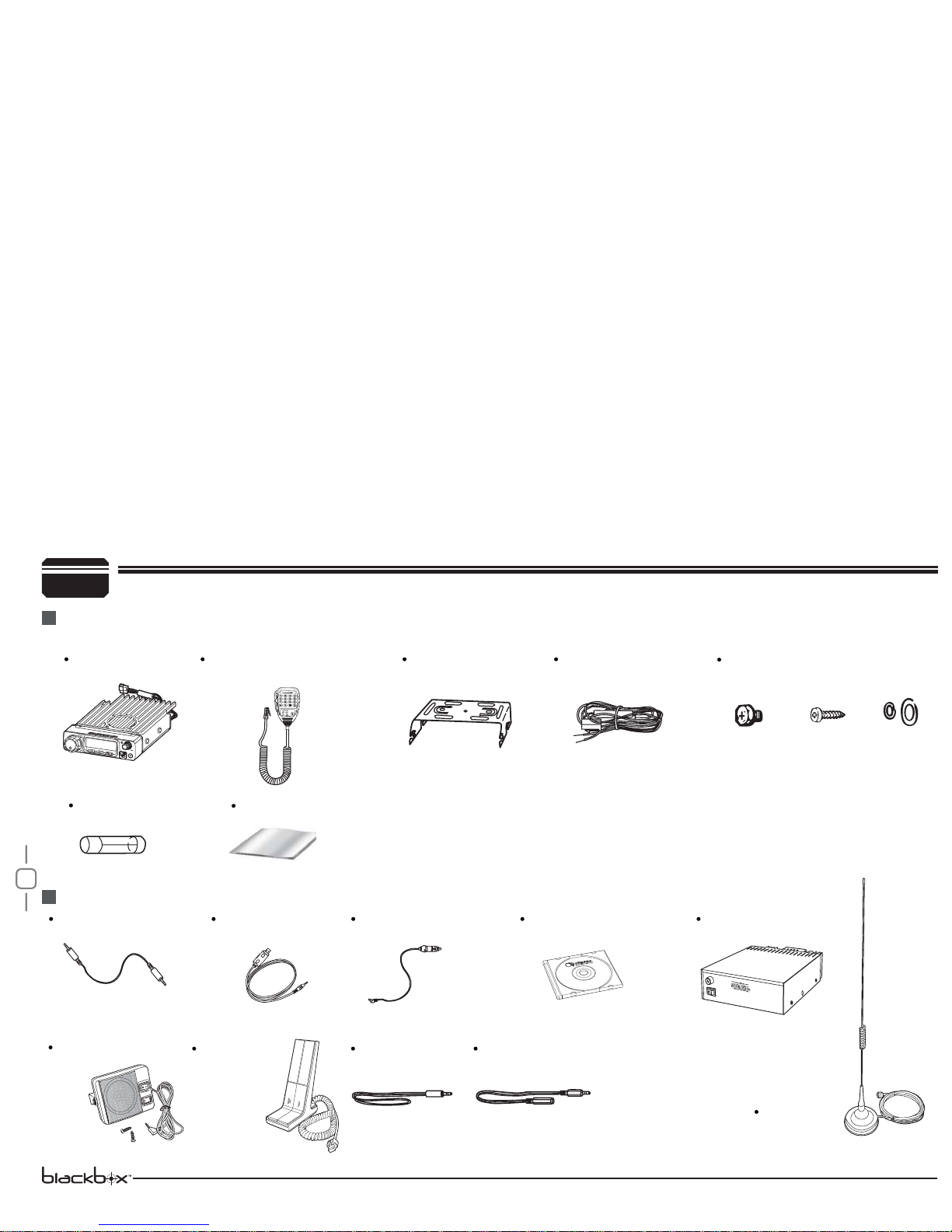
After carefully unpacking the transceiver, identify the items listed in the table below. We suggest you keep the box and packaging.
Transceiver
Spare Fuses
[QF-01]
Cloning Cable (CP50)
Desktop
Microphone
(QDM-01)
Alarm Cable A
[QL-01(A)]
Alarm Cable B (Extension line)
[QL-01(B)]
Car Antenna
(QCA-01)
USB Programming
Cable (PC50)
Cigar-Plug Connection
Line (QCC-01)
Programming Software
(QPS-588)
Regulated Power
Supply (QRP-01)
External Speaker
(SP-01)
User Manual
Microphone (QHM-03)
(with DTMF keyboard)
Mobile Mounting
Bracket (QMB-01)
DC Power Cable with
Fuse Holder(QPL-01)
Hardware Kit for Bracket
Black screws
)M4X8mm*
5QDT)RTT.12B*
Tapping screws
)M5X8mm*
5QDT)RTT.12C*
S-Washer
(QSS-01D)

3
To install the transceiver, select a safe, convenient location inside your
vehicle that minimizes danger to your passengers and yourself while the
vehicle is in motion. Consider installing the unit at an appropriate position
so that knees or legs will not strike it during sudden braking of your
vehicle. Try to pick a well ventilated location that is shielded from direct
sunlight.
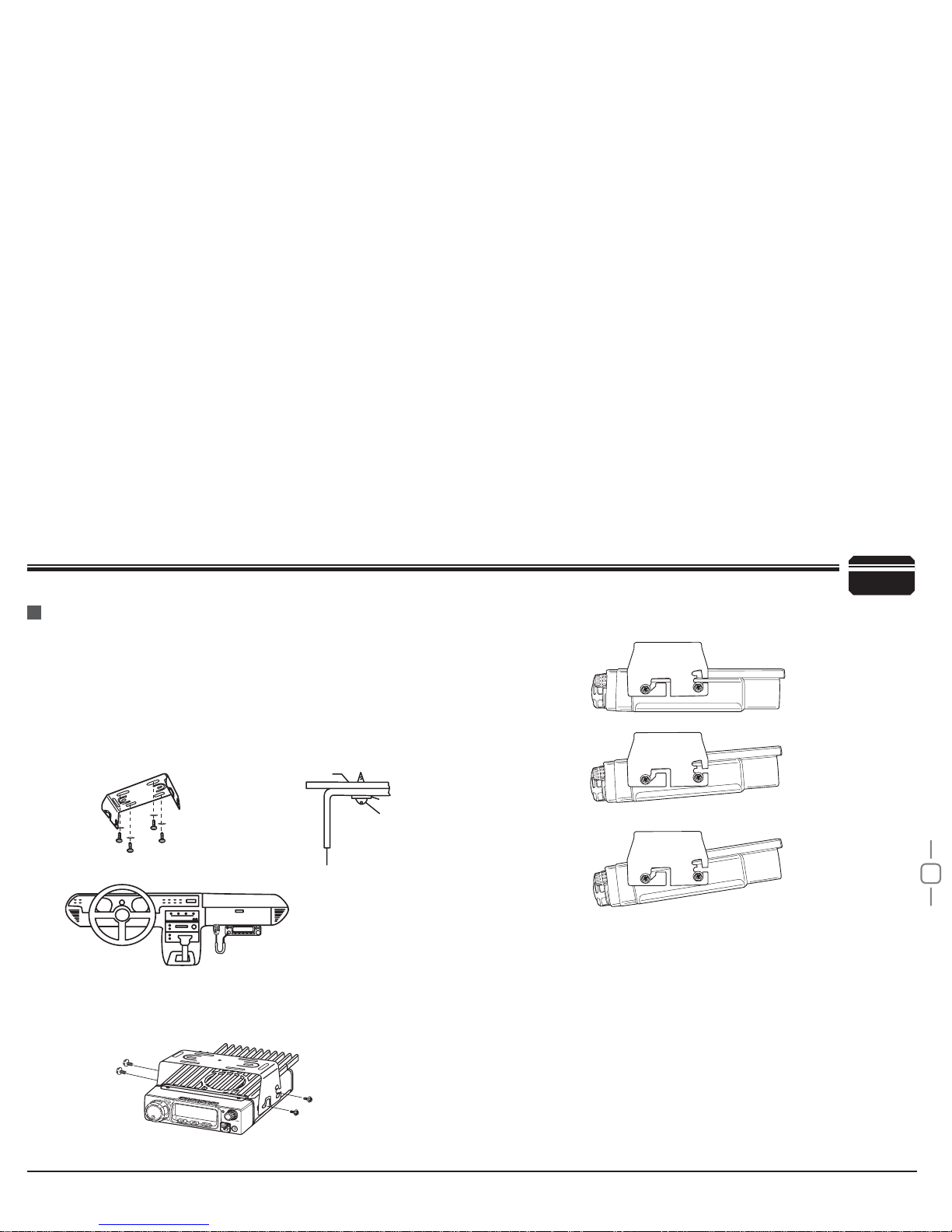
Install the mounting bracket in the vehicle using the supplied self-
1.
WDSSLQJVFUHZVSFVDQGÀDWZDVKHUVSFV
Position the transceiver, then insert and tighten the supplied
2.
hexagon SEMS screws.
Double check that all screws are tightened to prevent vehicle
vibration from loosening the bracket or transceiver.
3
Car body
Washer (M5)
Tapping screw
(M5x20mm)
Mounting bracket
Initial Installation
Mobile installation Determine the appropriate angle of the transceiver, using the 3 screw
hole positions on the side of the mounting bracket.

4
Connect the DC power cable to the transceiver's power supply
6.
connector.
Press
WKHFRQQHFWRUV¿UPO\WRJHWKHUXQWLOWKHORFNLQJWDEFOLFNV
If the ignition-key on/off feature is desired(optional feature),use the
3
Red
Black
Ext. Power jack
DC power cable
Initial Installation
DC Power Cable Connection
Mobile Operation
In many cars,the cigar-lighter plug is always powered. If this is the case, you
cannot use it for the ignition key on/off function.
The vehicle battery must have a nominal rating of 12V. Never
connect the transceiver to a 24V battery. Be sure to use a 12V
vehicle battery that has sufficient current capacity. If the current
to the transceiver is insufficient, the display may darken during
transmission, or transmitting output power may drop excessively.
When the ignition key is turned to ACC or ON(Start) position with
7.
the radio turned off, the power switch illuminates. The illumination
will be turned off when the ignition key is turned to the off position.
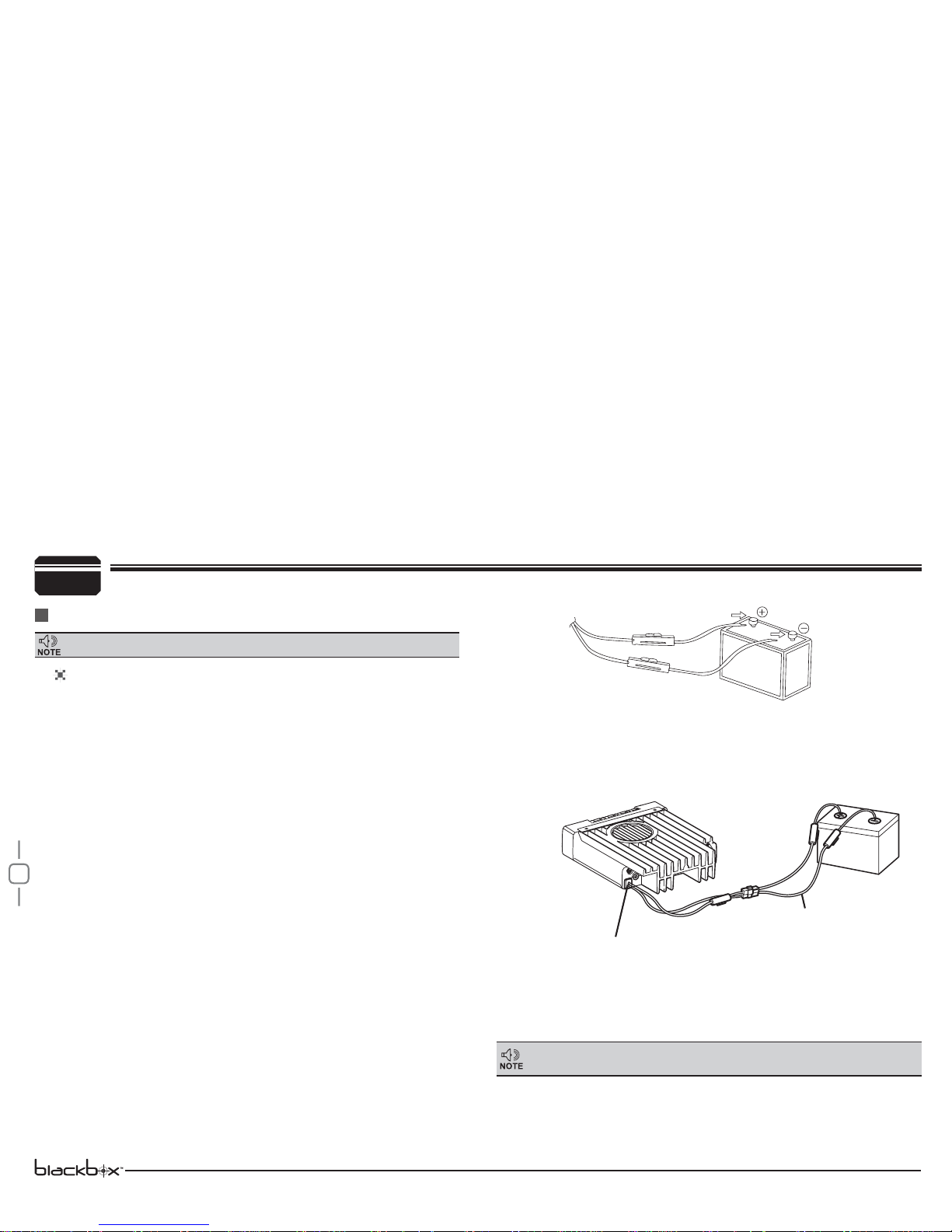
Route the DC power cable supplied with the transceiver directly
1.
to the vehicle's battery terminals using the shortest path from the
transceiver.
We recommend you do not use the cigarette lighter socket as
some
cigarette lighter sockets introduce an unacceptable voltage drop.
The entire length of the cable must be dressed so it is isolated from
heat, moisture, and the engine secondary (high voltage) ignition
system/ cables.
After installing cable, in order to avoid the risk of damp, please
2.
use heat-resistant tap to tie together with fuse box. Don't forget to
reinforce whole cable.
In order to avoid the risk of short circuit, please cut down
3.
connection with negative (-) of battery, then connect with radio.
Confirm the correct polarity of the connections, then attach the
4.
power cable to the battery terminals; red connects to the positive (+)
terminal and black connects to the negative (-) terminal.
Use the full length of the cable without cutting off excess even if
the
cable is longer than required. In particular, never remove the fuse
holders from the cable.
Reconnect any wiring removed from the negative terminal.
5.
optional QCC-01(For Cigar-Plug connection) cable. Connect one of
the cables between the ACC terminal or a Cigar-Plug that operates
with the vehicle ignition or ACC switch on the vehicle and EXT
POWER jack on the rear side of the unit.
Locate the power input connector as close to the transceiver as possible.

5
3
Red
Black
Regulated power supply (QRP-01)
DC power cable with fuse holder (QPL-01)
Regulated
power supply
(QRP-01)
Ext. Power jack
ACC terminal
Cigar-Plug connection
Initial Installation
Before connecting the DC power to the transceiver, be sure to switch
the transceiver and the DC power supply OFF.
Do not plug the DC power supply into an AC outlet until you make all
connections.
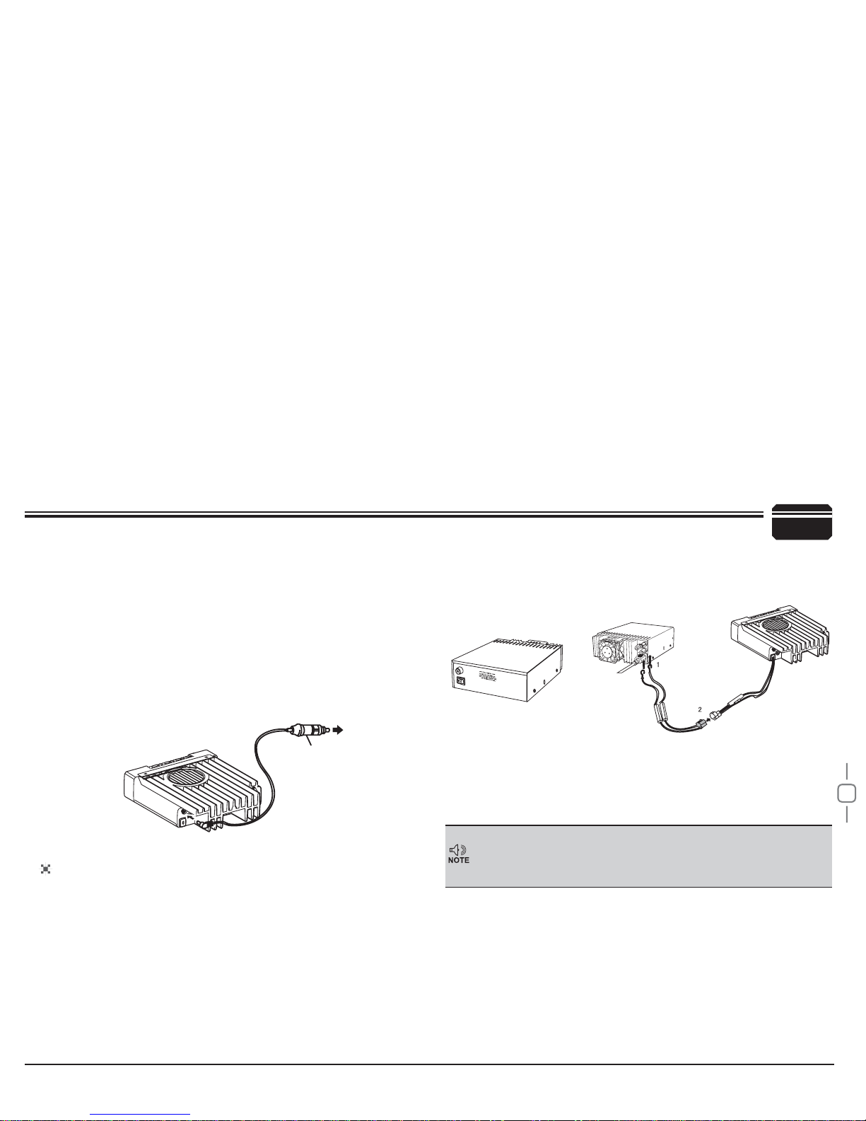
,QRUGHUWRXVHWKLVWUDQVFHLYHU IRU¿[HGVWDWLRQRSHUDWLRQ\RXZLOO
need a separate 13.8V DC power supply (not included) , power
supply( QRP-01) as optional accessories. Please contact local dealer
to require.
The recommended current capacity of your power supply is 12A.
Connect the DC power cable to the regulated DC power supply
1.
and ensure that the polarities are correct. (Red: positive, Black:
negative).
Do not directly connect the transceiver to an AC outlet.
Use the supplied DC power cable to connect the transceiver to a
regulated power supply.
Do not substitute a cable with smaller gauge wires.
To turn on the unit, press the power switch manually while it is
illuminated. (While ignition key is at ACC or ON position)
When the ignition key is turned to ACC or ON position with the
8.
radio's power switch on, the unit turns on automatically and the
power switch will be lit. Turn the ignition key to OFF position or
manually turn the power switch off to shut down the radio.
Using extra cable,power consumption:5MAH.
9.
Without this function,user can turn on/off radio by Power knob.
10.
Connect the transceiver's DC power connector to the connector
2. on
the DC power cable.
3UHVVWKHFRQQHFWRUV¿UPO\WRJHWKHUXQWLOWKHORFNLQJWDEFOLFNV
.
Fixed Station Operation
Indice
Altri manuali Black Box Radio