
BLUM RC66 Manuale utente

RC66
Radio Receiver
focuson productivity
Radio transmission
for touch probes
Installation instructions English
Type P03.6600-010


Content
by lum-Novotest 2010
3
1. Safety Rules...................................................................................4
2. System Overview..........................................................................4
2.1 Description.......................................................................................................4
2.2 Display Elements .............................................................................................6
2.3 Technical Data................................................................................................6
2.4 Area of Work ...................................................................................................7
2.5 Complete System ...........................................................................................7
3. Mechanical Installation ...............................................................8
3.1 Mounting Variants...........................................................................................9
4. Electrical Connection ................................................................12
5. Maintenance ..............................................................................12
. Order Numbers...........................................................................12
7. Radio Approval ..........................................................................13
Installation instructions interface IF59-A2 (P03.5900-000.011)
Keys:
CAUTION
Important advice for appliance protection
Advice to secondary literature
Additional advice
Tip
LED shines
LED flashes
Green Red lue Orange Violet
Abbreviations:
M
d
Tightening Torque
P03.6600-000.011
306600011_EN.docx
02.05.2011 version: V1A
Original operating instructions
Subject to technical change without any
notice
GN
GN
GN
VT
OG
BU
RD

Safety Rules
4
by lum-Novotest 2010
1. Safety Rules
CAUTION
Risk of short-circuit
Please separate connecting cable resp. plug connection off
circuit only.
2. System Overview
2.1 Description
The radio receiver is compatible with the LUM measuring devices TC series
(radio probes TC60, TC63-30). The receiver enables wireless communication
between the measuring devices and the NC control. Data transfer to the NC
control via IF59-A2 interface.
Fig. 2.1
(1a)
LED mode (2) cable
(1b)
LED battery (3) for mounting screws
(1c)
LED status (4) seal insert + O-Ring
(1d)
LED receive (at horizontal cable outgoing)
(1e)
LED transmit
90°
Mode
RC66
IF59-A2
P03.5900-010-A2
3
4
1a
1b
1c
1d
1e
2

System Overview
by lum-Novotest 2010
5
Fig. 2.2
Mode
max.Ø38
min. Ø20
30
42
Ø 44
9,5
Ø 3,3
Ø 6
3,2
M4
37
37
45
Ø 6,3

System Overview
by lum-Novotest 2010
2.2 Display Elements
LED LED colour
function
MODE (1a)
Standby
Mode TC1 …TC6
Pairing procedure
Battery (1b) Battery o.k.
Battery low
Status (1c) Initial position
Probe deflected
Receive (1d)
off No reception
Reception o.k.
Transmit (1e)
Send command
Tab. 2.1
2.3
Technical Data
Protection class IP68
Power supply 12 V DC / 100 mA via IF59-A2
Weight 600 g
Signal transmisson Radio transmission
Frequency band: 2,400 – 2,4835 GHz
Transmission power 0 d m
Transmitter / receiver range 15 m, see chap. 2.4
Minimum bending radius 60 mm (application: flexible)
Max. cable length 50 m
Storage temperature -20 °C ... +70 °C
Operating temperature +5 °C ... +50 °C
Tab. 2.2
Mode
Mode
U
RD
GN
GN
RD
OG
U
VT
GN
GN

System Overview
by lum-Novotest 2010
7
2.4 Area of Work
TC60 Area of work: RC66 Transmitter / receiver range:
Fig. 2.3
2.5 Complete System
Fig. 2.4
⇒Switch ON/OFF via radio signal
⇒Signal transmission for TC series
0°
0°
15°
30°
45°
60°
75°
15°
30°
45°
60° 75°
90°
16
14
12
10
6
15°
30°
45°
60°
75°
15°
30°
45°
60° 75° 90°
8
2
4
0°
15°
30°
45°
60° 75°
90°
16
14
12
10
15°
30°
45°
60° 75° 90°
8
2
4
6
RC66
TC60
IF59 - A2
Z-Nano
Aux
TC63-30

Mechanical Installation
8
by lum-Novotest 2010
3. Mechanical Installation
CAUTION
Risk of short-circuit
Damage by chips
Never install cables and hoses without protection.
Cables and hoses must always be protected against chips
(protective hose, protection spring, cover etc.).
CAUTION
Risk of short-circuit
Damage of the cable by sharp edges
Pls. deburr the sharp edges on the cable bushing and
mount edge protection!
CAUTION
•The system should be placed protected from coolant
and chips.
•Distance between probe and receiver:
Pay attention to chap. 2.4
•Keep distance to other radio systems

Mechanical Installation
by lum-Novotest 2010
9
3.1 Mounting Variants
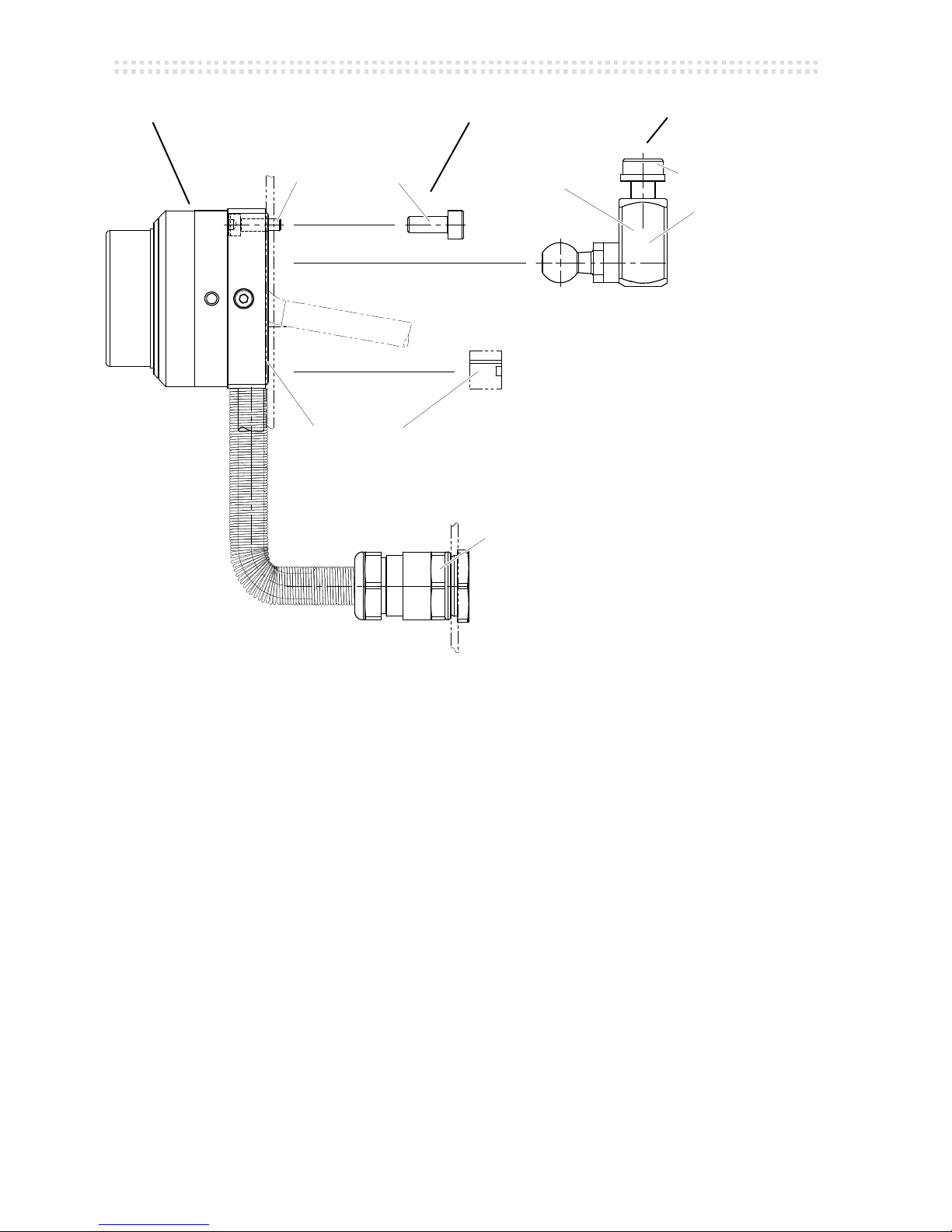
Cable outgoing horizontal:
Pollution of the system
Mount gasket (9a) and O-ring (9b)
Fig. 3.1
Cable outgoing vertical:
Fig. 3.2
4a 4b
Mechanical Installation
10
by lum-Novotest 2010
Variant 1 Variant 2 Variant 3 (option)
Fig. 3.3
(4a) seal insert
(4b) O-Ring
(5) universal holder (option)
Tightening torque:
DIN912 M3x10: M
d
= 1,3 Nm (max.)
DIN912 M4x10: M
d
= 3,0 Nm (max.)
DIN912 M6x12: M
d
= 10,5 Nm (max.)
Drilling template (scope of delivery)
M3 M4 M6
4a
P03.5600-010.254
5
4b
P03.5600-010.080
Altri manuali per RC66
2
Indice
Altri manuali BLUM Ricevitore


