BOPIXEL OPR407 Series Manuale utente

OPR407 Series DLP projector operating manual
Catalogue
一、 Precautions ......................................................................................................... 1
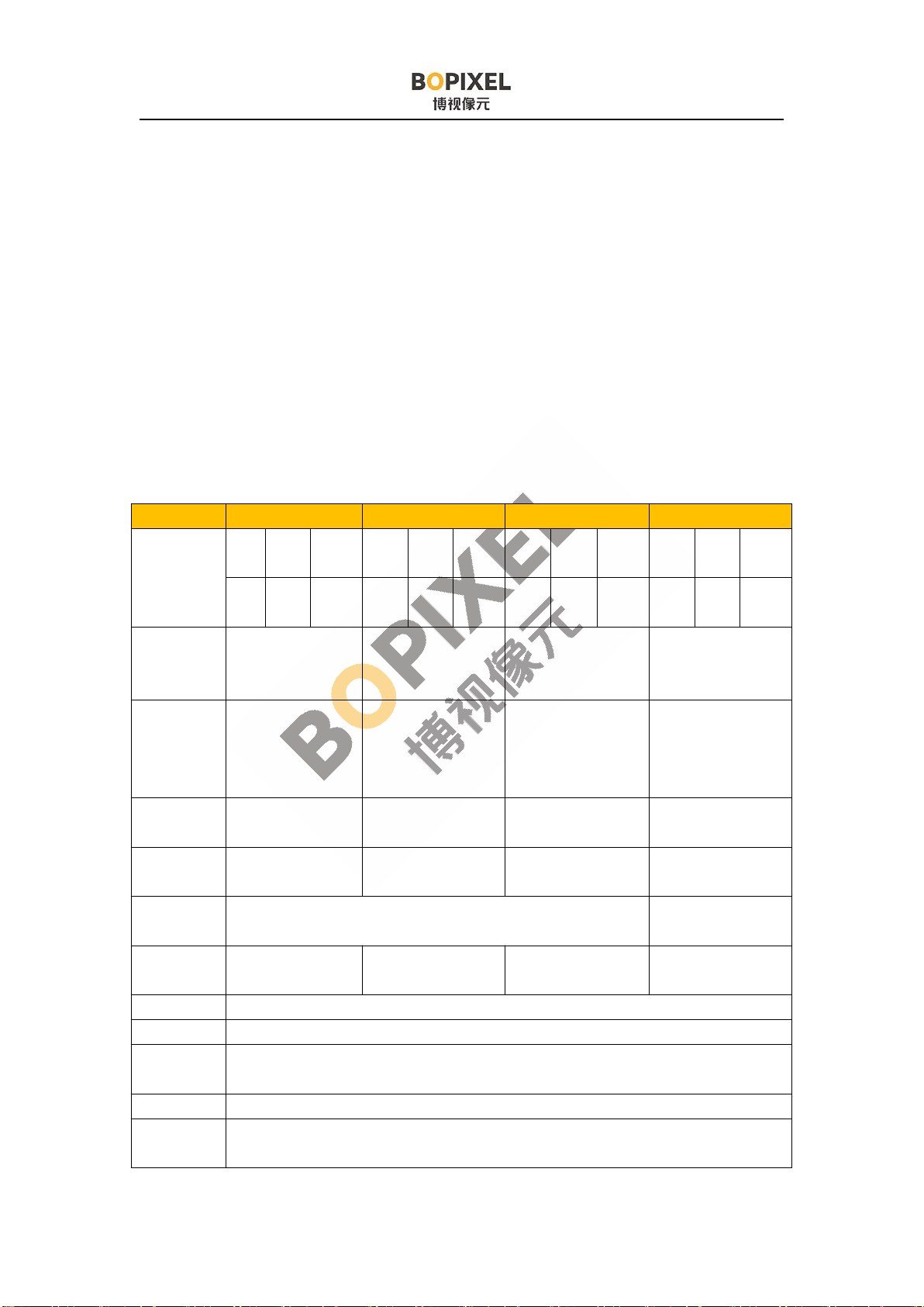
二、 Module Specifications ........................................................................................2
三、 Interfaces Introduction ......................................................................................5
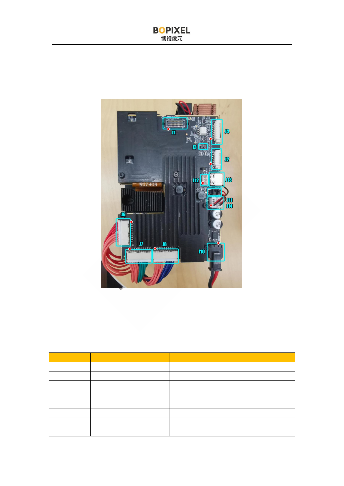
3.1 Connectors Positions Introduction ....................................................................5
3.2 Interfaces Description ....................................................................................... 6
3.2.1 J1 Extended video interface ....................................................................6
3.2.2 J2 I2C Interface .......................................................................................7
3.2.3 J3 External I2C Enable Jumper .............................................................. 7
3.2.4 J4 Trigger Interface .................................................................................7
3.2.5 J10 12V Power Connector ...................................................................... 8
3.2.6 J11 Fan Connector .................................................................................. 8
3.2.7 J14 External Power Supply Connector ................................................... 8
3.2.8 J12 USB internal connector .................................................................... 8
四、 Instruction .......................................................................................................... 9
4.1 Product Description .......................................................................................... 9
4.2 Software and Documents .................................................................................. 9
4.2.1 Software .................................................................................................. 9
4.2.2 Reference Documents ............................................................................. 9
4.3 Software Installation ....................................................................................... 10
4.3.1 GUI software .........................................................................................10
4.3.2 Others ....................................................................................................11
4.4 Hardware connection ...................................................................................... 11
4.4.1 Driver Installation ................................................................................. 11
4.5 GUI Instruction ............................................................................................... 12
4.5.1 Connect module to computer ................................................................12
4.5.2 "Display" mode to test patterns and images ......................................... 13
4.5.3 "light control" mode to customize stripe patterns .................................17
4.5.4 Firmware programming ........................................................................ 24
4.5.5 Debug instructions ................................................................................ 25
4.6 DLP advanced control mode ...........................................................................26
4.6.1 Precise brightness control ..................................................................... 28

4.6.2 Build-in stripe patterns ..........................................................................31
4.7 Make a Batch file ............................................................................................ 33
4.8 Make Firmware ...............................................................................................38
五、Appendix .............................................................................................................43
5.1 DLP4710EVM-LC Firmware Release Notes ................................................. 43
5.2 "Internal Patterns" mode operation steps ........................................................44
5.3 How to Modify the Specifications of Test Patterns? ...................................... 51
六、FAQ ..................................................................................................................... 53
6.1 How to Program the DLPC3479? ................................................................... 53
6.2 What is a 1D pattern? ......................................................................................53
6.3 Why would you want to use a 1D pattern? ..................................................... 53
6.4 What is a pattern set? ...................................................................................... 54
6.5 How many patterns can be stored in each pattern set? ................................... 54
6.6 How to change frame rate of internal pattern?............................................... 54
6.7 Why is there a minimum pre-exposure dark time and post-exposure dark time
limit? ..................................................................................................................... 55
6.8 What actually happens in pre-exposure dark time and post-exposure dark time?
.............................................................................................................................. 55
6.9 What timings are supported by Internal pattern streaming mode? ................. 56
6.10 Do these minimum darkfield times have to be calculated? .......................... 56
七、Guarantee ........................................................................................................... 57

1
一、 Precautions
Please read all instruments before use, otherwise the product
may be damaged.
1) The optical module is in the device and the circuit board is exposed, so do not
drop it from a height.
2) This device contains high-precision optical components, so please do not
disassemble without authorization.
3) The module is powered by 12V power supply. A 12V, 10A or higher current
adapter is suitable. Otherwise, it may cause the adapter to overcurrent and power off
when the brightness is increased.
4) DMD flat cable connector has a limited service life, so it is not allowed to unplug
the cable without authorization.
5) It is strictly forbidden to Unplugging the DMD flat cable when the module is
power on condition. This will damage the DMD.
6) Please pay attention to anti-static measures before use. Static electricity will
cause damage to the main chips or DMD.
7) This module is turned on when it is powered on. If it does not work properly,
please contact us.
8) Note: The GUI software version is 2.2.0.6 in this document, and the
operating system is Win10 x64.

2
二、 Module Specifications
1) Module projection resolution: 1920 x 1080
2) Max frame speed of image input: 60Hz (2D and 3D) for 1080p
3) Internal storage frame rate: 1440Hz (1 bit) , 180Hz (8bit)
4) Integrated internal storage can store more than 1000 graphics.
5) Maximum Power: 100W
6) Support USB connection to official GUI control software, and external I2C and
SPI connection to control module and firmware programming
7) Support trigger input and output. 3.3V or 5V (default) power output is optional.
8) Support parallel or BT656 video input.
OPR407 series (DLP4710)
Type OPR407185 OPR407700 OPR407100 OPR407185S
Working
distance
mm
MI
N
TY
P
MA
X
MI
N
TY
P
MA
X
MI
N
TY
P
MA
X
MI
N
TY
P
MA
X
10
0185 450 300 700 1200 300 100
02000 100 185 450
Screen size
(TYP)
mm
140*79 604*340 1054*593 158*128*92
Depth of
focus
(TYP)
mm
-55~+100 -200~+300 -500~+500 -30~+40
Throw
Ratio 1.32 1.16 0.94 1.32
Precision
um 73 315 549 73
Mode Orthographic projector Scheimpflug/Tilt
structure
Dimension
mm 127*73*47 132*73*47 127*73*47 130*78*55
Distortion <0.5%
Resolution 1920*1080
Uniformity
JBMA >90%
Contrast 500:1
Light
source RGB LED

3
OPR407185 Dimension OPR407185 Dimension
OPR40718S schematic diagram

4
OPR407185S Screen size

5
三、 Interfaces Introduction
The connector location and pin 1 location are marked in the image above. Pin 1
is marked with a triangle on the circuit board, please pay attention to the comparison.
3.1 Connectors Positions Introduction
Connector Matching plug type Description
J1 AXT650124 Extended video interface
J2 51021-0600 I2C interface
J3 2.0mm Jumper I2C enable
J4 51021-0800 Trigger interface
J5 AXT680124 DMD flat cable
J6 87439-1000 Red LED output
J7 87439-1000 Green LED output
J8 87439-1000 Blue LED output

6
J10 43645-0200 12V Power supply
J11 51021-0400 12V Power for fan
J14 51021-0400 12V, 5V, 3.3V power supply
J12 51021-0400 USB interface internal connector
J11 USB type C USB interface
3.2 Interfaces Description
3.2.1 J1 Extended video interface
Pin Definition Description Pin Definition Description
1 PDATA21 Video Signal
Input
50 PDATA22 Video Signal Input
2 PDATA20 49 PDATA23
3 PDATA19 48 GND
4 PDATA18 47 PCLK Video Signal
control
5 PDATA17 46 DATEN_CM
D
6 PDATA16 45 VSYNC_WE
7 GND 44 HSYNC_CS
8 PDATA15 Video Signal
Input
43 PDM_CVS_T
E
9 PDATA14 42 3DR_D
10 PDATA13 41 E_SCL External I2C
interface
11 PDATA12 40 E_SDA
12 PDATA11 39 EX_I2C_OE pull up 3.3V to
enable external I2C
13 PDATA10 38 EXT_CLK External SPI
interface
14 PDATA9 37 EXT_MOSI
15 PDATA8 36 EXT_MISO
16 GND 35 EXT_CSZ
17 PDATA7 Video Signal
Input
34 EXT_PROJ_O
N
pull up 3.3V to
power on the DLP
18 PDATA6 33 MCU_ACK I2C reply sent by
MCU
19 PDATA5 32 MCU_REQ I2C request sent by
GUI
20 PDATA4 31 GND
21 PDATA3 30 S_HOST_IRQ Slave reports error
22 PDATA2 29 M_HOST_IR
Q
Master reports error
23 PDATA1 28 SPI_BUS_SE External SPI

7
L channel switching
24 PDATA0 Video Signal
Input
27 EXT_SPI_EN External SPI
Enable
25 GND 26 GND
3.2.2 J2 I2C Interface
It has the same function as the J1 flat cable, and use a general connector, which
is convenient for customers to use.
Pin Definition Description
1 E_SCL External I2C bus clock
2 E_SDA External I2C bus data
3 EX_I2C_OE External I2C bus is enabled. After the voltage is pulled up to
3.3V, the external I2C is enable, and the USB to I2C channel is
closed.
4 NC
5 EXT_PROJ_ON The voltage is pulled up to 3.3V to turn on, and the 0V voltage is
used to turn off.
6 GND Signal Ground
3.2.3 J3 External I2C Enable Jumper
It is used to force enable the external I2C interface. Connecting the jumper can
enable external I2C interface, and then connection with GUI software using USB will
be disabled.
3.2.4 J4 Trigger Interface
Pin Definition Description
1 GND Signal Ground
2 PWR_SEL Trigger signal level power supply. 3.3V or 5V can be
available (using different resistors)
3 PATTERN_R
DY
Pattern_ready signal defined by GUI
4 TRIG_OUT2 Trigger output 2 defined by GUI, open-drain output,
pulled up to 5V with a 1k resistor
5 TRIG_IN Trigger input defined by GUI, with optocoupler
isolation, 3.3V~24V compatible
6 EXT_T5

8
7 TRIG_OUT1 Trigger output 1 defined by GUI,open-drain output,
pulled up to 5V with a 1k resistor
8 NC
3.2.5 J10 12V Power Connector
Pin Definition Description
1 12V Power 12V Power Input. Voltage reaching 15V will trigger
overvoltage protection
2 GND Signal Ground
3.2.6 J11 Fan Connector
Pin Definition Description
1 GND Signal ground
2 12V 12V power supply for fan
3 NC
4 NC
3.2.7 J14 External Power Supply Connector
Pin Definition Description
1 GND Signal ground
2 12V 12V power supply for fan
3 5V 5V power supply
4 3.3V 3.3V power supply
3.2.8 J12 USB internal connector
Pin Definition Description
1 GND Ground
2 DP Signal positive
3 DN Signal negative
4 VBUS USB power input
Questo manuale è adatto per i seguenti modelli
4
Indice
Altri manuali BOPIXEL Proiettore


