BRIO TROE600PRISM Guida utente
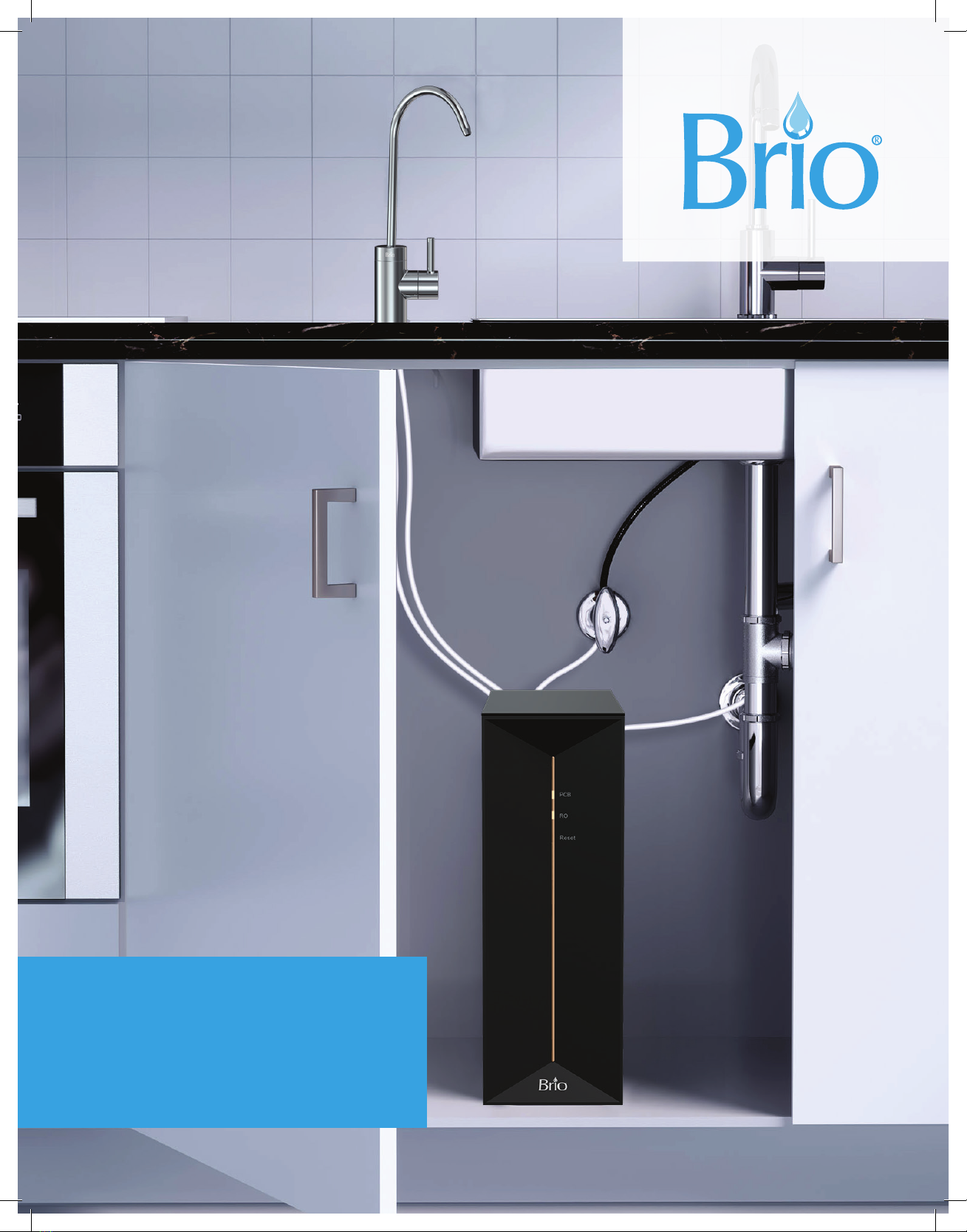
Tankless 1.5:1 RO Filtration System
with Stainless Steel Faucet
Setup Manual
Model No.: TROE600PRISM

2
Table of Contents
Safety Information . . . . . . . . . . . . . . . . . . . . . . . . . . . . . . . . . . . . . . . . . . . . . . . . . . . . . . . . . . . . . . . . . . . 3
Intended Use........................................................................3
Package Contents . . . . . . . . . . . . . . . . . . . . . . . . . . . . . . . . . . . . . . . . . . . . . . . . . . . . . . . . . . . . . . . . . . .4
Product Features ....................................................................5
Indicator Panel Description . . . . . . . . . . . . . . . . . . . . . . . . . . . . . . . . . . . . . . . . . . . . . . . . . . . . . . . . . . . . . 5
Specifications .......................................................................6
Materials Needed ....................................................................6
Installation ..........................................................................7
Installation Overview . . . . . . . . . . . . . . . . . . . . . . . . . . . . . . . . . . . . . . . . . . . . . . . . . . . . . . . . . . . . . . . . . . 7
Connect to the Cold Water Supply. . . . . . . . . . . . . . . . . . . . . . . . . . . . . . . . . . . . . . . . . . . . . . . . . . . . . . . 7
Install the Reverse Osmosis Drain Saddle . . . . . . . . . . . . . . . . . . . . . . . . . . . . . . . . . . . . . . . . . . . . . . . . 8
Install the Faucet . . . . . . . . . . . . . . . . . . . . . . . . . . . . . . . . . . . . . . . . . . . . . . . . . . . . . . . . . . . . . . . . . . . . . 10
Complete the Installation . . . . . . . . . . . . . . . . . . . . . . . . . . . . . . . . . . . . . . . . . . . . . . . . . . . . . . . . . . . . . . . 11
Operation.......................................................................... 11
Start Up the Filtration System . . . . . . . . . . . . . . . . . . . . . . . . . . . . . . . . . . . . . . . . . . . . . . . . . . . . . . . . . . . 11
Start Water Purification. . . . . . . . . . . . . . . . . . . . . . . . . . . . . . . . . . . . . . . . . . . . . . . . . . . . . . . . . . . . . . . . . 11
Shut Down ...........................................................................11
Care and Maintenance. . . . . . . . . . . . . . . . . . . . . . . . . . . . . . . . . . . . . . . . . . . . . . . . . . . . . . . . . . . . . . . 12
Filter Replacement Schedule . . . . . . . . . . . . . . . . . . . . . . . . . . . . . . . . . . . . . . . . . . . . . . . . . . . . . . . . . . 12
Replacing the Filters . . . . . . . . . . . . . . . . . . . . . . . . . . . . . . . . . . . . . . . . . . . . . . . . . . . . . . . . . . . . . . . . . . 12
Flushing the Filters . . . . . . . . . . . . . . . . . . . . . . . . . . . . . . . . . . . . . . . . . . . . . . . . . . . . . . . . . . . . . . . . . . . 13
Troubleshooting ....................................................................13
Warranty...........................................................................15

3
Safety Information
WARNING: To reduce risk of injury and property damage, you must read this entire manual before
assembling, installing, and operating the filtration system.
• Installation needs to comply with state and local laws and regulations.
• If the power cable is damaged, do not use. Contact customer service for a replacement.
• Avoid storing in an area exposed to intense sunlight as this can cause damage to components.
• Do not store in or expose the device to temperatures lower than 32 °F (0 °C). The ideal temperature range
is39–100 °F (4–38 °C).
• The device must be installed or relocated by a professional technician due to the risk of electric shock and
product damage.
• The best working pressure for this device ranges from 15 to 100 PSI. Install a pressure increasing or
decreasing device if the water pressure is lower or higher than this level.
• For use with municipal tap water only. Not for use with well or underground water.
• Do not place magnetic devices near the device as damage could occur.
• Do not place heavy objects on the device.
• Do not allow children near the device without adult supervision.
• Do not pull the power cord as this could cause damage. To unplug the unit, grasp the power cord by the
plug and pull directly from socket.
• Do not plug in or unplug with wet hands.
• Do not place combustible substances near the device. Keep away from heat sources and open flames.
• Install this device near a floor drain.
• If the device is not going to be used for a long period of time, unplug the unit from the power source and
close the shut-o valve.
Intended Use
This filtration system is intended to be used in household and similar applications such as:
• Sta kitchen areas in shops, oces, and other working environments
• Farm houses
• Hotels, motels, and bed-and-breakfast environments
• Residential-type environments
• Catering and similar non-retail applications
This appliance is not intended for use by persons (including children) with reduced physical, sensory, or mental
capabilities, or lack of experience and knowledge, unless they are given supervision or instruction concerning
the use of appliance by a person responsible for their safety.
4
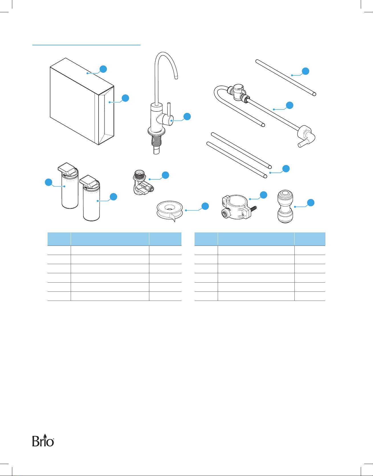
Package Contents
A
D
F
J
L
K
G
E
H
I
B
C
Part Description Quantity Part Description Quantity
A RO filtration unit 1 G Plumbers tape 1
B Faucet 1 H Drain saddle 1
C Filter compartment cover 1 I RO waste water tube 1
D Feed water adapter 1 J Shut-o valve tube 1
E PCB filter 1 K Faucet tubing 2
F RO filter 1 L 1/4 in. Quick connector 1
5
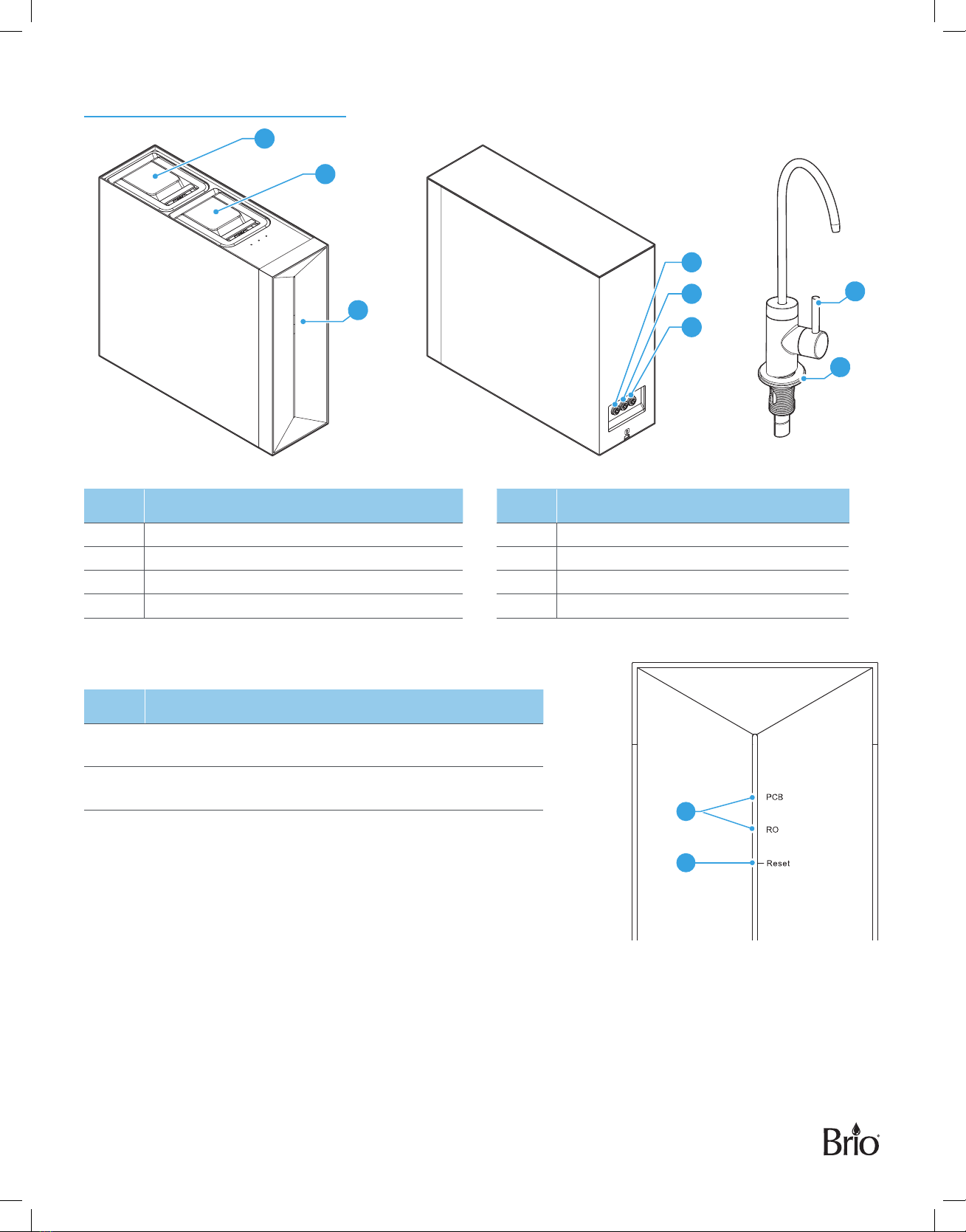
Product Features
3
7
8
7
4
5
6
2
1
Part Description Part Description
1 PCB filter compartment 5 Filtered water connection
2 RO filter compartment 6 Waste water connection
3 Filter indicator 7 Filtered water lever
4 Inlet water connection 8 Faucet O-ring
Indicator Panel Description
Item Description
9Filter indicator lights – When blinking, indicates it is
time to change filters (RO or PCB).
10 Reset button – Touch and hold for 3 seconds to reset
the system after changing filters.
9
10
6
Specifications
Model No. TROE600PRISM
Product Dimensions
(WxHxD)
5.4 x 15.4 x 16.9 in.
(13.8 x 39.0 x 43.0 cm)
Daily Production Rate 600 GPD
Purified Flow Rate 1.5 LPM
Feed Water Requirement Municipal tap water
Feed Water Pressure 15–100 psi
Feed Water Temperature 39–100 °F (4–38 °C)
Filtration System PCB and RO
Rated Voltage / Frequency 220–240 V / 50/60 Hz
Rated Power 60 W
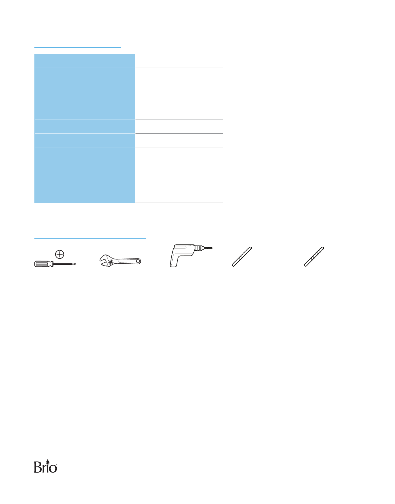
Materials Needed
Phillips-Head
Screwdriver
Adjustable Wrench Power Drill 1/4" Drill Bit
(for Drain Saddle)
1" Drill Bit
(for Faucet
Mounting Hole)
7
Installation
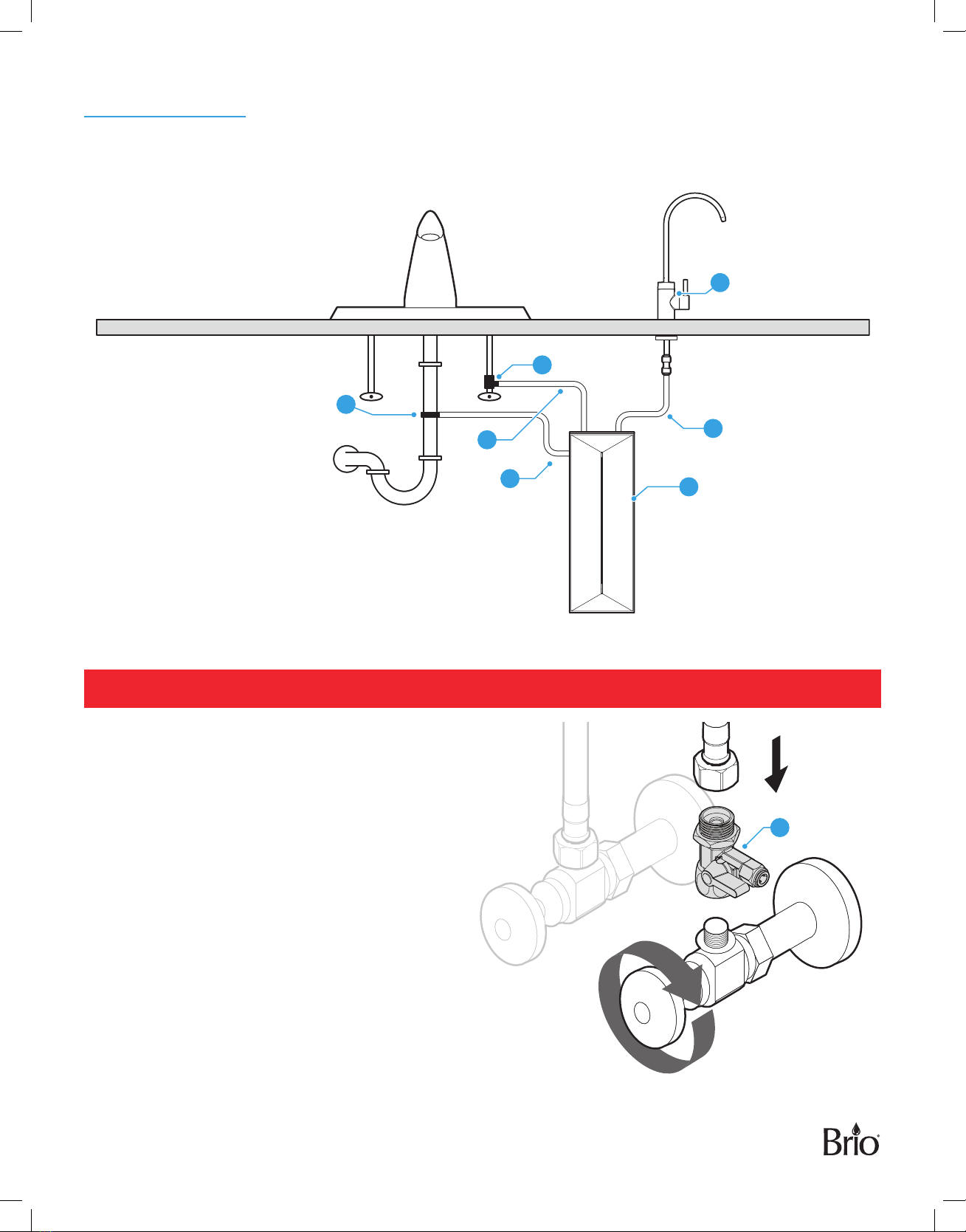
1. Installation Overview
H
I
J
D
K
B
A
2. Connect to the Cold Water Supply
CAUTION: DO NOT CONNECT THIS WATER LINE TO A HOT WATER SUPPLY LINE. The water supply to the
unit MUST be from the COLD WATER LINE. Using HOT WATER will severely damage your filters.
A. Turn o and then disconnect the current cold
water supply line.
B. Connect the feed water adapter (D) to the cold
water supply line.
C. Connect the cold water supply line on top of
the feed water adapter (D).
NOTE: An extra adapter nut is included on top
of the feed water adapter (D) to attach to
a 3/8 in. or 1/2 in. feed plumbing line.
D
8
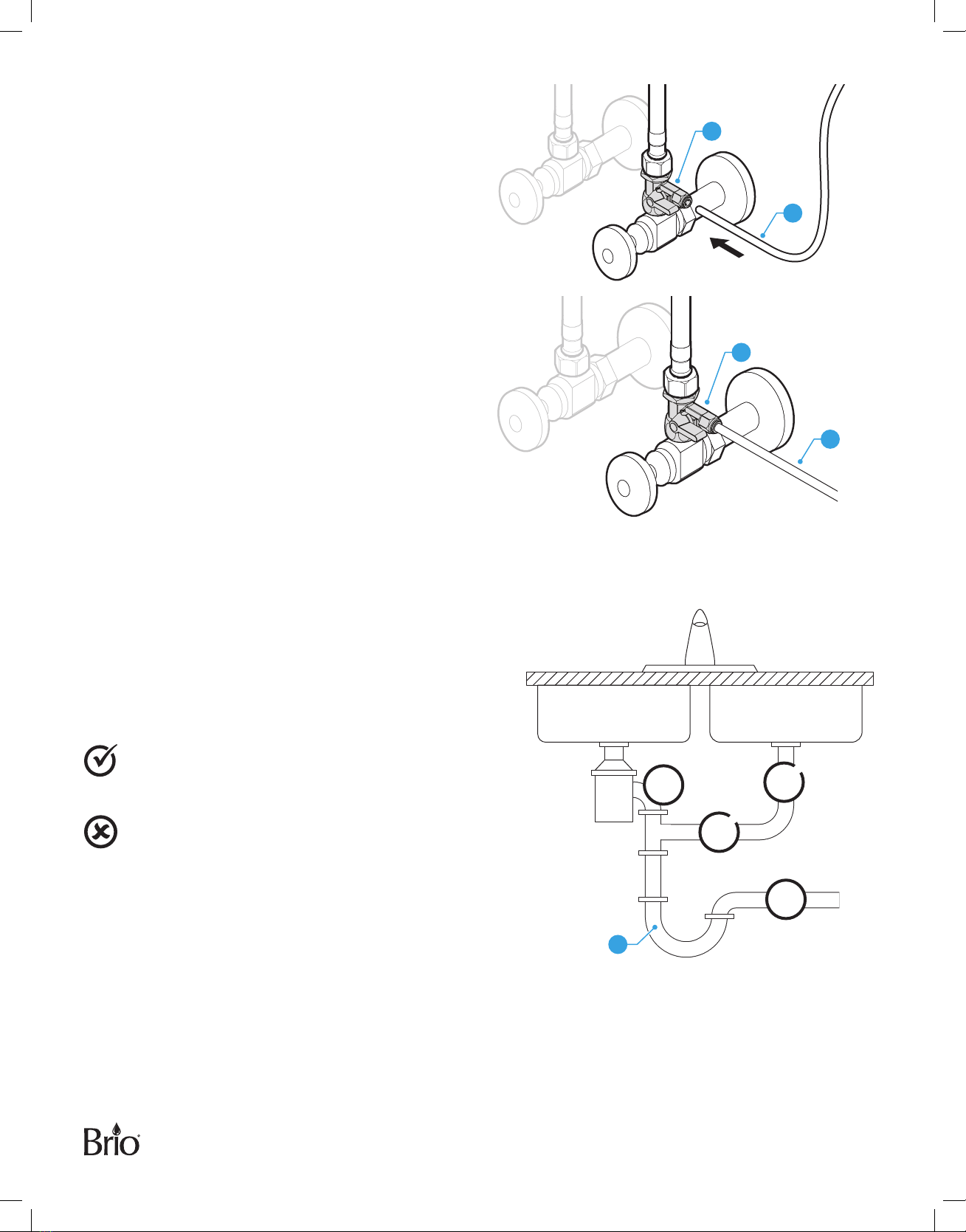
D. Insert the shut-o valve tube (J) straight into
the quick connector piece of the feed water
adapter (D).
E. Tighten the nut on the feed water adapter(D).
D
J
F. Gently tug on the shut-of valve tube (J) to
ensure a secure connection with the feed water
adapter (D). D
J
3. Install the Reverse Osmosis Drain Saddle
The RO filter assembly requires a drain line connection
to be installed, which removes rejected water to the
sewer. The drain saddle connects the drain line from
the dispenser to your drain pipe. The drain saddle
is designed to fit around a standard 1.5 in. OD (outer
diameter) drain pipe.
Always install the drain saddle above the
P-trap(11). Ensure the drain saddle is in place on
the vertical or horizontal section of the pipe.
To avoid clogging the drain line with debris, do
not install the drain saddle on a section of piping
that is located after the drain pipe meets a
garbage disposal or dishwasher drain.
11
9
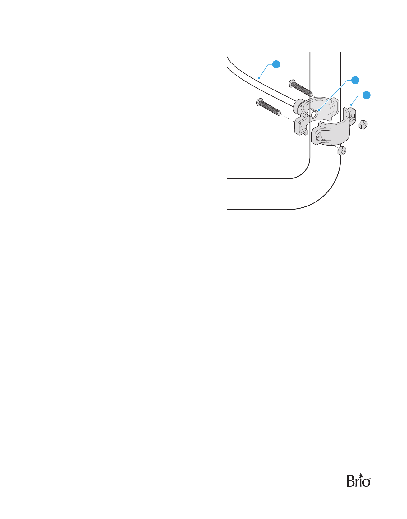
To install the Reverse Osmosis (RO) drain saddle:
A. Determine the location for your drain saddle (H)
and then make a mark on the drain pipe for the
opening(12).
B. Use your drill and a 1/4 in. drill bit to create a hole at
the mark, ensuring you only drill through one side of
the drain pipe.
C. Find the half of the drain saddle (H) with the hole in
the center, remove the backing from the foam gasket,
align the gasket with the hole on the drain saddle(H),
and stick the adhesive side of the gasket to the drain
saddle(H).
D. Position both halves of the drain saddle (H) on the
drain pipe with the saddle’s opening aligned over
the drilled hole, and insert your drill bit through the
saddle(H) and drilled hole to ensure proper alignment.
E. Secure both ends of the drain saddle (H) together
using the bolts and nuts, but do not overtighten.
F. Connect the RO waste water tube (I) to the drain
saddle(H).
I
H
12
10
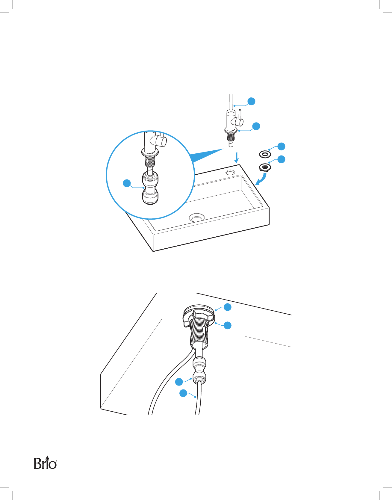
4. Install the Faucet
A. Ensure that you have a mounting hole in your sink or countertop for this faucet. If you do not, create a
mounting hole no less than 1.0–1.2 in. (2.54–3.0 cm).
B. Remove the washer (13) and lock nut (14) from the faucet (B). Ensure that you leave the O-ring (8) on the faucet.
C. Attach the 1/4 in. quick connector (L) to the stem outlet.
B
8
13
14
L
D. Insert the faucet into the mounting hole and secure in place underneath the sink with washer (13) and locknut
(14).
E. From underneath the sink, attach the faucet tube (K) to the 1/4 in. quick connector (L).
13
14
L
K
Indice
Altri manuali BRIO Sistema di filtraggio dell'acqua

BRIO
BRIO ROSL500 Guida utente

BRIO
BRIO G20-U Guida utente

BRIO
BRIO amphora ROP100 Guida utente

BRIO
BRIO CROS2400 Manuale utente

BRIO
BRIO amphara UF100FWHT Guida utente

BRIO
BRIO G10-U Guida utente

BRIO
BRIO amphora Guida utente

BRIO
BRIO FUS300R Manuale utente

BRIO
BRIO 3 Stage System Manuale utente

BRIO
BRIO AQUUS TROE600COL Guida utente


