
Canon PSC 2000 Manuale utente
2000 Fire Door-Fan Manual updated 2002-05-28 Page 1 of 58
2000 Fire Door-Fan Manual
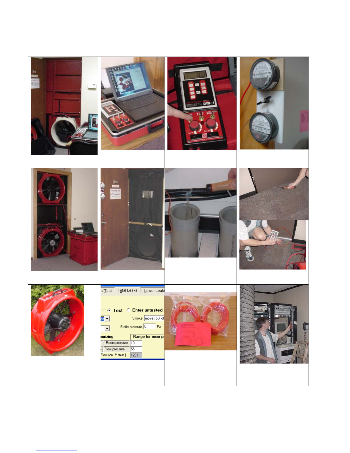
Single Blower Panel Set
Up
with Model N digital
console OR, Model L digital
control panel OR, Model E analog
gauge clip
Large room testing with
2 Blowers
Or, E43 Aluminum
Frame Set Up
Leak check at + 15Pa
Room pressure
Smoke test &
measure static pressure
Range Selection Room and Flow
Pressure Readings
Windy test conditions Mixing or NO mixing?

2000 Fire Door-Fan Manual updated 2002-05-28 Page 2 of 58
What to do if room fails.
Lower leak tests using:
Flex-duct ceiling
neutralization
Lower leak tests using:
Plastic-on-Ceiling
procedure
Run from CA2001
Lower leak Estimates
using: Leak audit
Field Calibration
Tall doorways
Sub-floor Only tests using
Floor neutralization
procedure
Packing up and moving
equipment
Large building Testing
…rent additional
equipment if needed
Recalibration of
Retrotec Infiltrometer
Troubleshooting and
repair

2000 Fire Door-Fan Manual updated 2002-05-28 Page 3 of 58
Single Blower Panel Set Up
Select a doorway where the air will be blown into
the largest space so the air can find its way back to
the leak. Set the panel bag close to the door.
Open panel bag and remove the Blower Panel with
the 22-inch hole in it.
Open Blower Panel and position back edge against
the doorstop.
Pull top strap tight and secure strap in the nylon
cleat. Press the loop against the Velcro to keep strap
ends neat.

2000 Fire Door-Fan Manual updated 2002-05-28 Page 4 of 58
Cinch lower strap tight and secure strap in cleat. The small fill-in sheet is positioned first in the
groove. It fills in the gap for doors up to 36”
Smooth down the fill-in sheet from top to bottom Place the large X-Panel in the top of the doorway.
Cinch and lock the pull strap to secure the panel. Place blower case next to the doorway.

2000 Fire Door-Fan Manual updated 2002-05-28 Page 5 of 58
Hook the bottom foot on the blower through the
hole in the center of the panel.
Align the nylon block on top of the blower with the
panel cutout, insert and rotate the blower till the
top is horizontal to lock it into the panel.
The blower is mounted in the Flow Away position.
This is always first. When the test is complete in
this direction, the blower is removed and installed
with the Flow Towards the operator.
Blower is upright and locked in place.
2000 Fire Door-Fan Manual updated 2002-05-28 Page 6 of 58
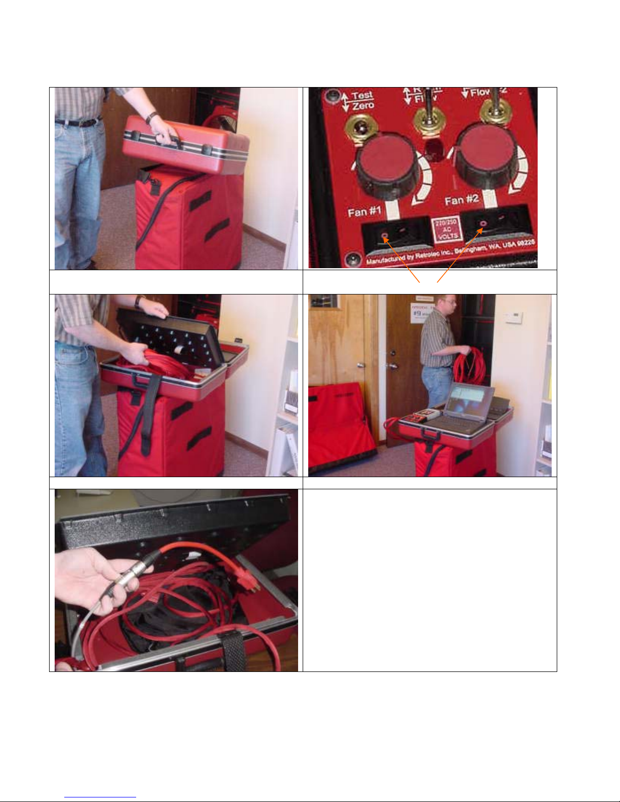
Set up Model N digital console
Place Laptop Console on blower case. Set rocker switches OFF by pressing the “0” so
blowers don’t come on accidentally.
Remove the control cords Place the cords next to the panel set.
Power to console comes from:
1. Blower receives power from wall.
Cord from console picks up this
power to run the printer, computer
and thermometers.
2. When blower is not plugged in, the
console can get power from the short
adapter plug that fits onto the end of
the umbilical cord then goes to a
wall socket.

2000 Fire Door-Fan Manual updated 2002-05-28 Page 7 of 58
Your laptop computer power supply plugs
into the female plug inside the console.
The power supply cord is then led through
this hole to the computer above.
2000 Fire Door-Fan Manual updated 2002-05-28 Page 8 of 58
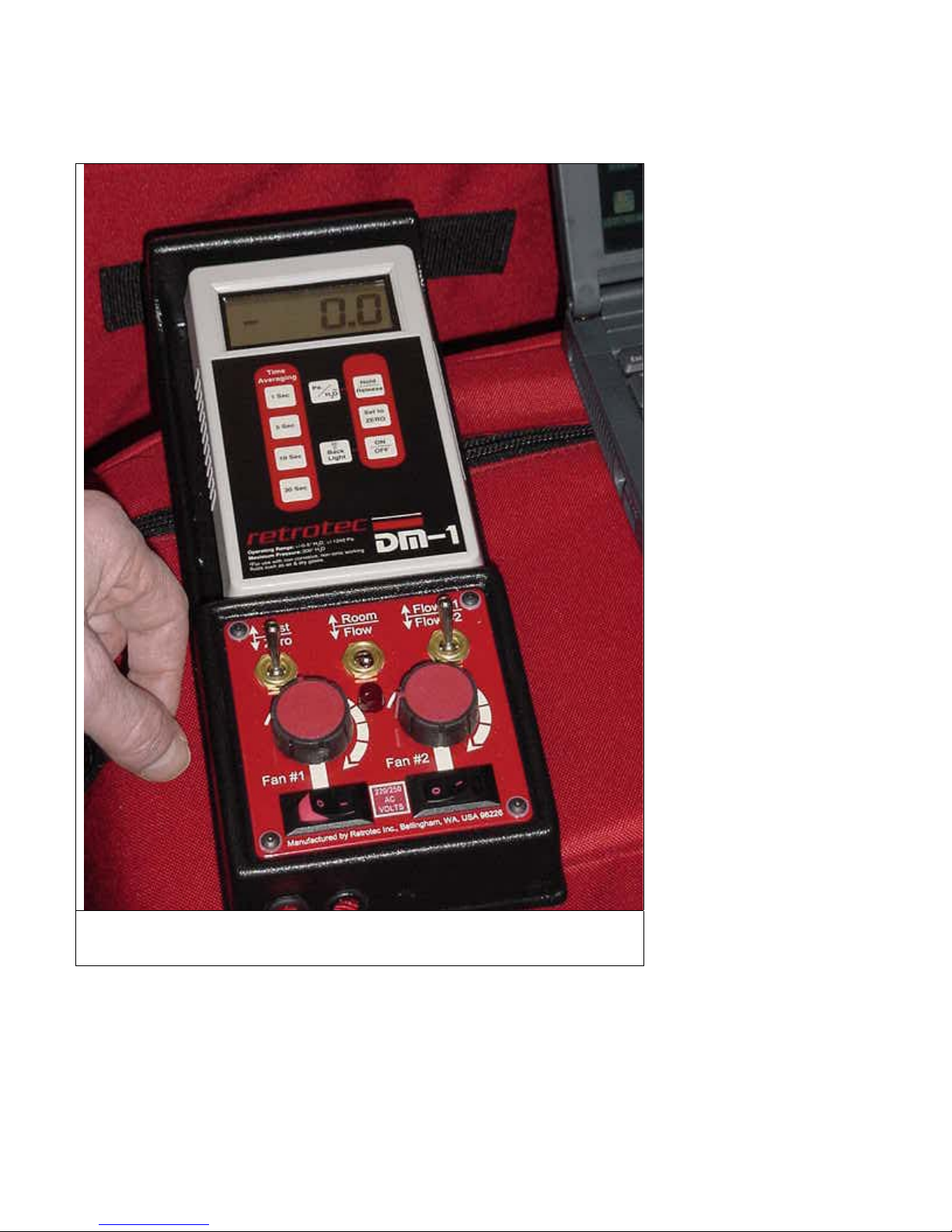
OR, Model L digital control panel for Models L64 and L63
The control panel can sit on top of the blower case with your laptop beside it.
2000 Fire Door-Fan Manual updated 2002-05-28 Page 9 of 58
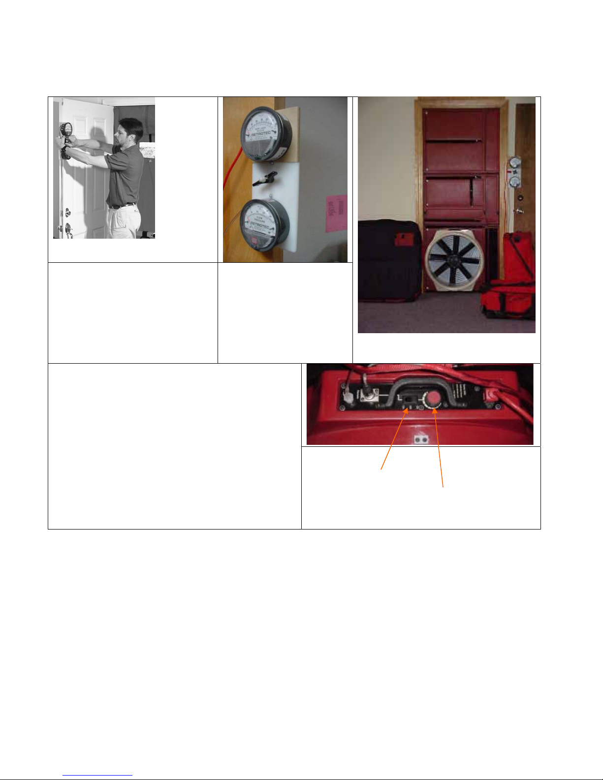
OR, Model E analog gauge clip for models E43, E53, E54
The Gauge Clip attaches to the door
or the Aluminium frame.
1. Loosen knob on gauge plate to
accommodate door thickness.
2. Hold gauges at eye level.
3. Rotate clamp to grip door.
4. Tighten knob.
Gauges mounted on door.
Top 60-gauge slides up and
off to be used as handheld
as needed.
Zero gauges by blowing in the tubes and capping them
off with your thumb so the gauge stays at the top of its
range for 30 seconds. If the gauge falls while capping
the tube, there is a leak, stop to locate and fix it. Let
the gauge fall back down and zero with small
screwdriver supplied. Do not turn more than 3 turns!
After another 30 seconds of gently tapping the gauge
front, adjust the zero screw at the bottom of each
gauge until it reads zero with the small slotted blade
screwdriver. Tap the gauge with your finger to
remove the mechanism's friction (hysteresis), and re-
zero if necessary.
Move rocker switch to the right then turn the
blower mounted speed control.

2000 Fire Door-Fan Manual updated 2002-05-28 Page 10 of 58
OR, DM-1 digital gauge for models J64
OR, DM-1 digital gauge
The digital gauge can be hand held and used to
measure static pressure, room pressure and flow
pressure. Connect a tube from the panel to the right
hand port of the DM-1 to get room pressure. Then
connect a tube from the DM-1 to the blower to get
flow pressure.
Questo manuale è adatto per i seguenti modelli
1
Indice


