Comet System P8610 Manuale utente

COMET SYSTEM
www.cometsystem.cz
P8610 intelligent thermometer
with PoE
P8631 intelligent 3-channel transducer
with PoE
USER MANUAL

IE-SNC-P86xx-01
2
©Copyright: COMET System, Ltd.
Is prohibited to copy and make any changes in this manual, without explicit agreement of
company COMET System, Ltd. All rights reserved.
COMET System, Ltd. makes constant development and improvement of their products.
Manufacturer reserves the right to make technical changes to the device without previous
notice. Misprints reserved.
Manufacturer is not responsible for damages caused by using the device in conflict with
this manual. To damages caused by using the device in conflict with this manual can not be
provide free repairs during the warranty period.

IE-SNC-P86xx-01
3
Table of contents
Introduction........................................................................................................................................................4
General safety rules .....................................................................................................................................4
Device description and important notices...............................................................................................5
Getting started....................................................................................................................................................6
What is needed for operation ....................................................................................................................6
Mounting the device....................................................................................................................................6
Device settings .............................................................................................................................................7
Checking functions......................................................................................................................................9
Device function description...........................................................................................................................10
Alarm limits ................................................................................................................................................10
Settings using TSensor software..............................................................................................................11
Setup via Telnet..........................................................................................................................................12
Factory configuration................................................................................................................................13
Communication protocols .............................................................................................................................14
Website........................................................................................................................................................14
SMTP –sending e-mails...........................................................................................................................14
SNMP ..........................................................................................................................................................15
Modbus TCP ..............................................................................................................................................15
SOAP...........................................................................................................................................................16
Syslog...........................................................................................................................................................17
SNTP ...........................................................................................................................................................17
Troubleshooting...............................................................................................................................................18
I forgot the device IP address..................................................................................................................18
I can not connect to the device...............................................................................................................18
Error1 is displayed instead the measured value....................................................................................19
Error2 is displayed in all channels instead the measured value..........................................................19
I forgot the password for setup...............................................................................................................19
Technical specifications..................................................................................................................................20
Dimensions.................................................................................................................................................20
Basic parameters ........................................................................................................................................21
Operating terms .........................................................................................................................................22
End of operation .......................................................................................................................................23
Technical support and service .................................................................................................................23
Preventive maintenance............................................................................................................................23
Optional accessories........................................................................................................................................24
Temperature probe DSTR162/C............................................................................................................24
Power supply Adapter A1825..................................................................................................................24
Device case holder for RACK 19" MP046 ...........................................................................................24
Probes holder for RACK 19" MP047 ....................................................................................................24
Dual Lock MD036 ....................................................................................................................................24
Database software DBS Sensor monitor ...............................................................................................25

IE-SNC-P86xx-01
4
Introduction
This chapter provides basic information about device. Before starting please read
this manual carefully.
P8610 Intelligent Thermometer and P8631 Transducer are used to measure temperature
using a digital sensor DS18B20. Temperature can be displayed in °C or °F. Communication
with the device is realized via Ethernet network. Device can be powered from external
power supply adapter or by using power over Ethernet –PoE.
P8610 Thermometer has compact design and measures the temperature in place of
installation. To P8631 Transducer is possible connect up to three probes. Temperature
probes are available as accessories.
General safety rules
The following summary is used to reduce the risk of injury or damage the device.
To prevent injury, please follow instructions in this manual.
The device can be services only by a qualified person. The device contains no
serviceable parts inside standard means.
Don’t use the device, if it doesn’t work correctly. If you think, that the device is
not working correctly, let check it by qualified service person.
Don’t disassemble the device. It’s forbidden to use the device without the cover. Inside the
device can be a dangerous voltage and may be risk of electric shock.
Use only the appropriate power adapter according to manufacturer specifications and
approved according to relevant standards. Make sure, that the adapter does not have
damaged cables or covers.
Connect the device only to network elements approved according to relevant standards.
Where power over Ethernet is used, the network infrastructure must be compatible with
IEEE 802.3af standard.
Connect and disconnect the device properly. Don’t connect or disconnect Ethernet cable
or probes, if the device is powered.
Chapter
1
IE-SNC-P86xx-01
5
The device may be installed only in prescribed areas. Never expose the device higher or
lower temperatures than is allowed. The device has not improved resistance to moisture.
Protect it from dripping or splashing water and do not use at areas with condensation.
Don’t use device in explosive environments.
Don’t stress the device mechanically.
Device description and important notices
This chapter contains informations about basic features. Also there are
important notices concerning to functional safety.
Values from the device can be read using an Ethernet connection. The following formats
are supported:
Web pages with user changeable look
Modbus TCP protocol
SNMPv1 protocol
SOAP protocol
The device can also be used to check measured values and if the limit is exceeded, device
sends warning messages. Possible ways to sending warning messages:
Sending e-mails up to 3 e-mail addresses (SMTP authentication is not
supported in current firmware version)
Sending SNMP traps up to 3 configurable IP addresses
Displaying the alarm status on web page
Sending messages to Syslog server
The device setup can be made by the TSensor software or via Telnet. TSensor software can
be free downloaded from the manufacturer’s website. Also you will find there latest
firmware for your device.
If you want to use PoE, you must use PoE switch compatible with IEEE 802.3af standard.
As a low cost solution can be recommended Repotec switch RP-PE8T/4.
Reliability of warning messages delivering (e-mail trap), depends on actual
availability of necessary network services. The device should not be used for
critical applications, where malfunction could cause to injury or loss of human
life. For highly reliable systems, redundancy is essential. For more information
please see standard IEC 61508.
Never connect the device directly to the Internet. If it is necessary connect the
device to the internet, properly configured firewall must be used. Firewall can
be partially replaced with the NAT.

IE-SNC-P86xx-01
6
Getting started
Here you can find informations necessary to put newly purchased equipment to
operation. This procedure is only informative.
What is needed for operation
To install the unit you need to the following equipment. Before installation check if it’s
available.
P8610 Thermometer or P8631 Transducer
power supply adapter 5V/250mA or switch with PoE. Before using the device
is necessary to decide which way of powering will be used.
RJ45 LAN connection with appropriate cable
free IP address in your network
for P8631 Transducer up to 3 temperatures probes type DSTR162/C
Mounting the device
check if the equipments from previous chapter are available
install the latest version of TSensor software. This software is used to all
device settings
TSensor software can be free downloaded from the manufacturer’s website.
Software can be also supplied on CD.
contact your network administrator to obtain following informations for the
connection to the network:
IP address:
_____._____._____._____
Gateway:
_____._____._____._____
Netmask:
_____._____._____._____
also check if there is no IP address conflict when you connect the device to
network for the first time. The device has factory set the IP address to
Chapter
2
IE-SNC-P86xx-01
7
192.168.1.213. This address must be changed according to informations from
the previous point. When installing several new devices, connect them to the
network one after another.
connect DSTR162/C probe at P8631 Transducer
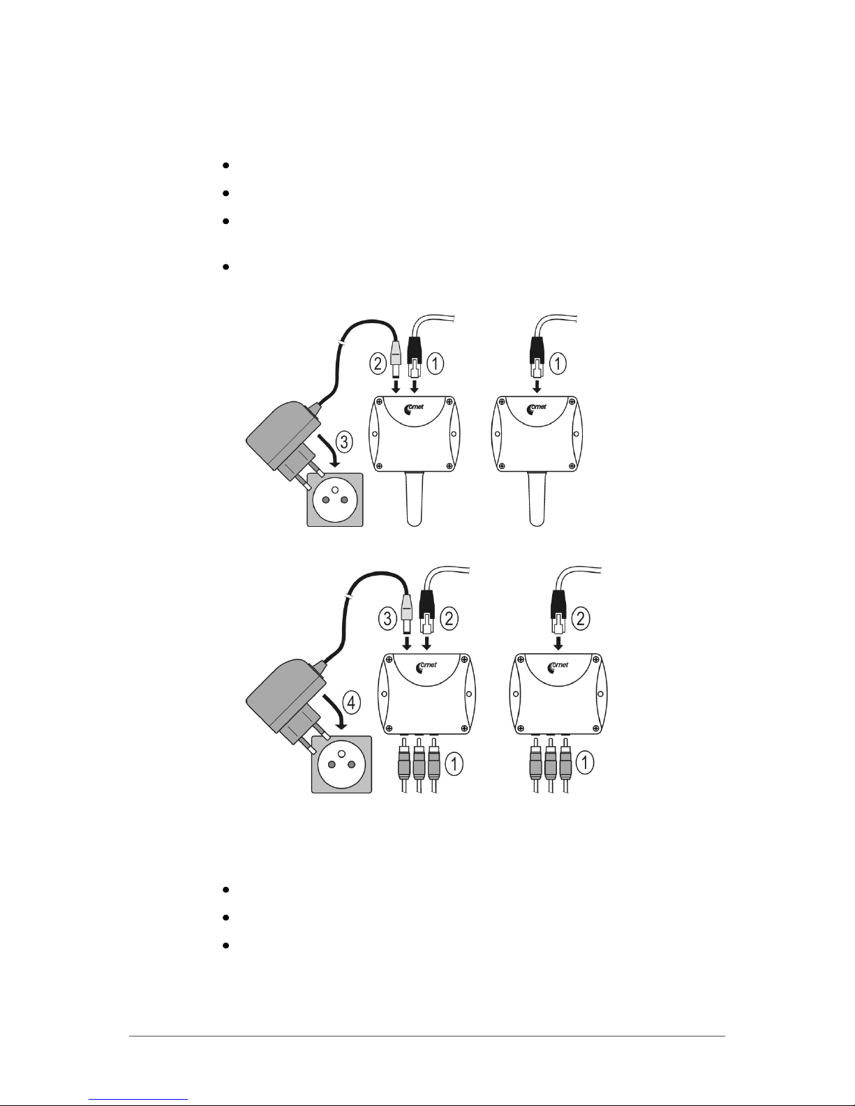
connect the Ethernet connector
if the power over Ethernet (PoE) is not used, connect the power adapter
5V/250mA
LEDs on LAN connector should blink after connecting the power
P8610 Thermometer connection (power supply adapter, Power over Ethernet):
P8631 Transducer connection (power supply adapter, Power over Ethernet):
Device settings
run configuration software TSensor on your PC
switch to an Ethernet communication interface
press Find device...

IE-SNC-P86xx-01
8
the window shows all available devices on network
click to Change IP address to set new address according to network
administrator instructions. If you need to use DHCP server for obtain IP
address set 0.0.0.0. If your device is not show, then click Help! My device
wasn’t found! Then follow the instructions. MAC address is on product
label. The device is factory set to IP 192.168.1.213.
gateway may not be entered if you want to use the device only in local
network. If you set the same IP address which is already used, the device will
not work correctly and there will be collisions on the network. If the device
detects a collision of IP address then reboot is performed automatically.
IE-SNC-P86xx-01
9
after changing IP address device is restarted and new IP address is assigned.
Restart of the device takes about 10 seconds.
connect to device using TSensor software and check the measured values. If
P8631 Transducer values are not displayed, it’s necessary to find probes using
button Search probes.
set the other parameters (alarm limits, SMTP server, etc.). Settings are saved
after click on button Save changes.
Checking functions
The last step is to check measured values on the device website. In the address bar of the
web browser, enter the device IP address. If the default IP address was not changed, then
insert http://192.168.1.213.
Displayed web page lists actual measured values. If the web pages are disabled, you can see
text ACCESS DENIED. If the measured value exceeds the measurement range or probe
is not correctly installed, then is shown Error1 value. If the channel is switched off, the
web site displayed OFF instead of the value.
IE-SNC-P86xx-01
10
Device function description
This chapter describes basic device configuration. There is a description of
settings using TSensor software and via Telnet.
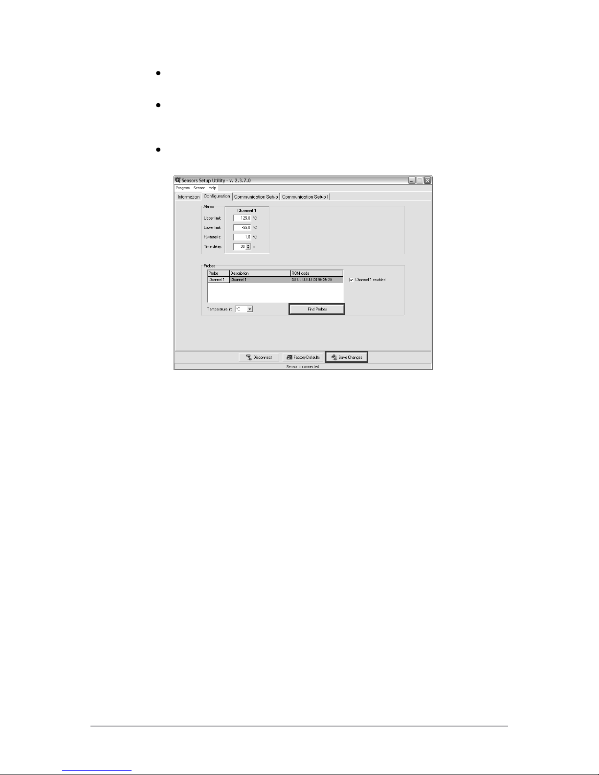
Alarm limits
Alarm limits can be set at bookmark Configuration in TSensor software. For each
measurement channel is possible to set upper and lower limits of temperature, time-delay
for alarm activation (0 –65535s) and hysteresis for alarm clearing.
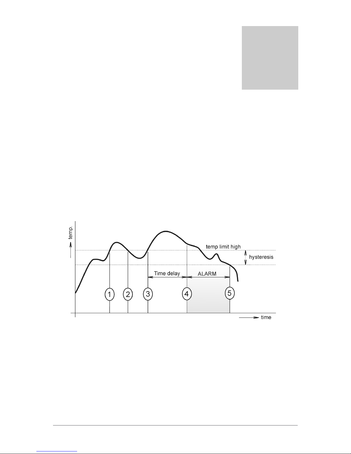
Example of setting the limit to the upper alarm limit:
In Point 1 the temperature exceeded the limit. From this time, the time-delay is counting.
Because at point 2 the temperature dropped below the limit value before the time delay
expired, alarm was not set.
In Point 3 the temperature has risen over limit again. During the time-delay the value does
not drop below the set limit, and therefore was in Point 4 caused alarm. At this moment
were sent e-mails, traps and set alarm flag on website, SNMP and Modbus.
The alarm lasted up to Point 5, when the temperature dropped below the set hysteresis
(temperature limit –hysteresis). At this moment was active alarm cleared.
When alarm occurs, alarm messages will be sent. But if alarm persists alarm messages will
not be sent repeatedly. In case of power failure or reset the device (e. g changing the
configuration) will new alarm state evaluated and new alarm messages will be send.
Chapter
3
Questo manuale è adatto per i seguenti modelli
1
Indice
Altri manuali Comet System Termometro


