Page 4
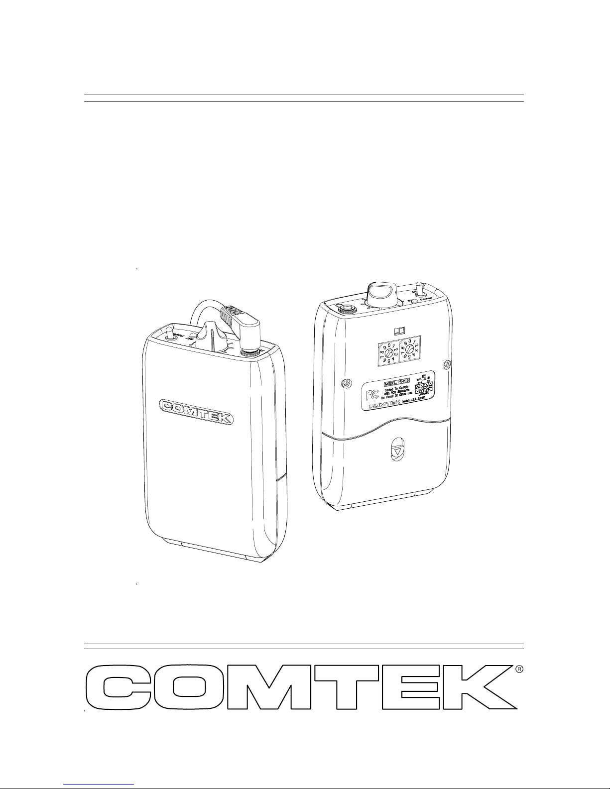
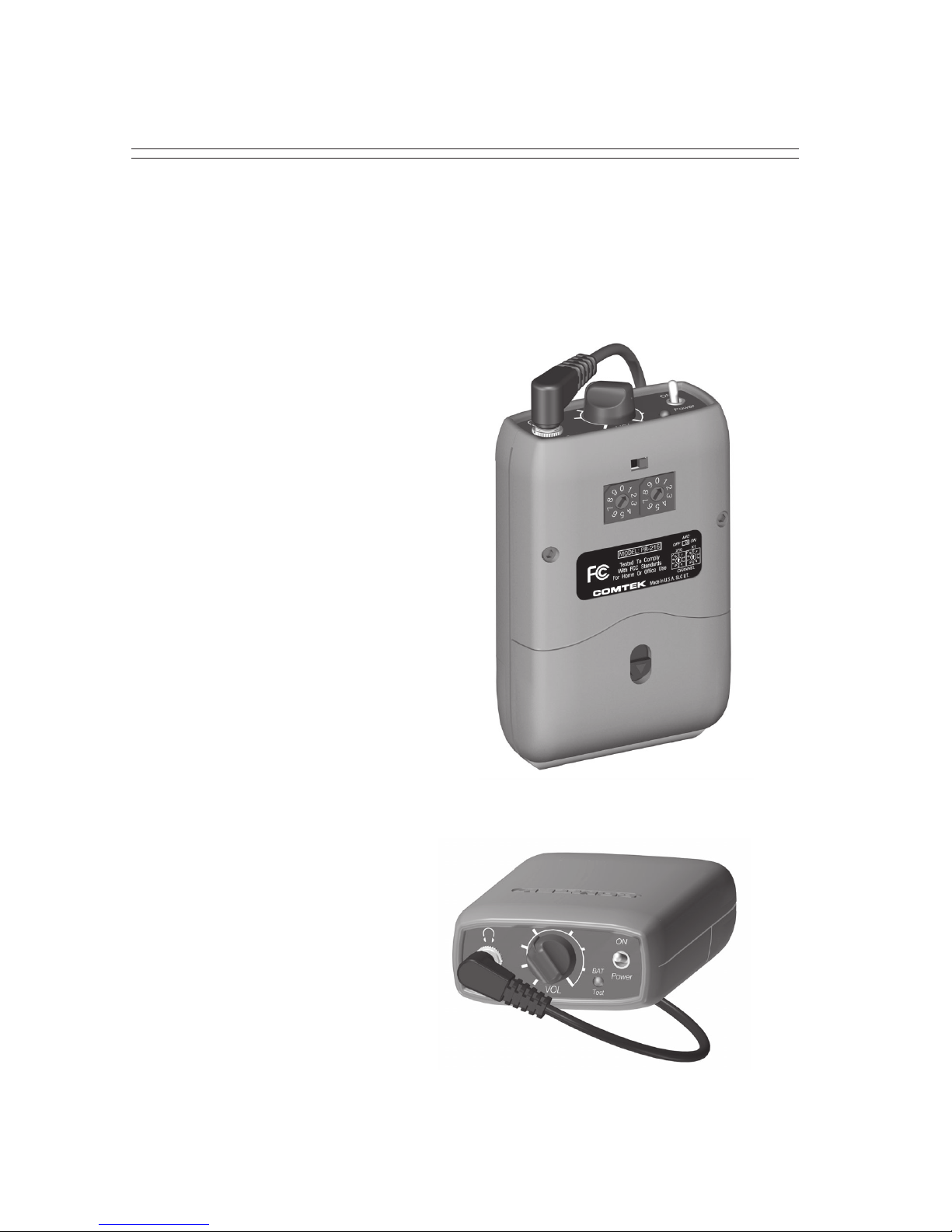
PR-216 OPERATING INSTRUCTIONS
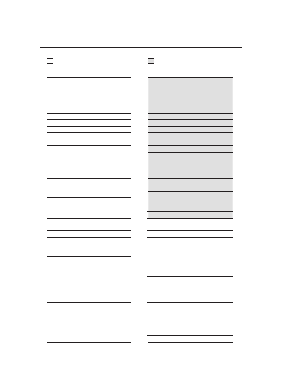
Frequency Selection (216-217 MHz)
The PR-216 personal receiver can operate on one of 76 available channels
between 216 MHz and 217 MHz. COMTEK’s channel designations
indicate both standard non-companded channels and
high-fidelity, companded channels. Channels 1-40
are non-companded channels offering compatibility
with other manufacturers. Channels 41-60 are
high-fidelity, companded channels for use with
COMTEK transmitters. Channels 61-79 are
standard non-companded channels for compatibility
with other manufacturers transmitters. COMTEK
transmitters automatically transmit the proper mode when set
to channels 1-40 for non-companded or 41-60 for companded
channels.
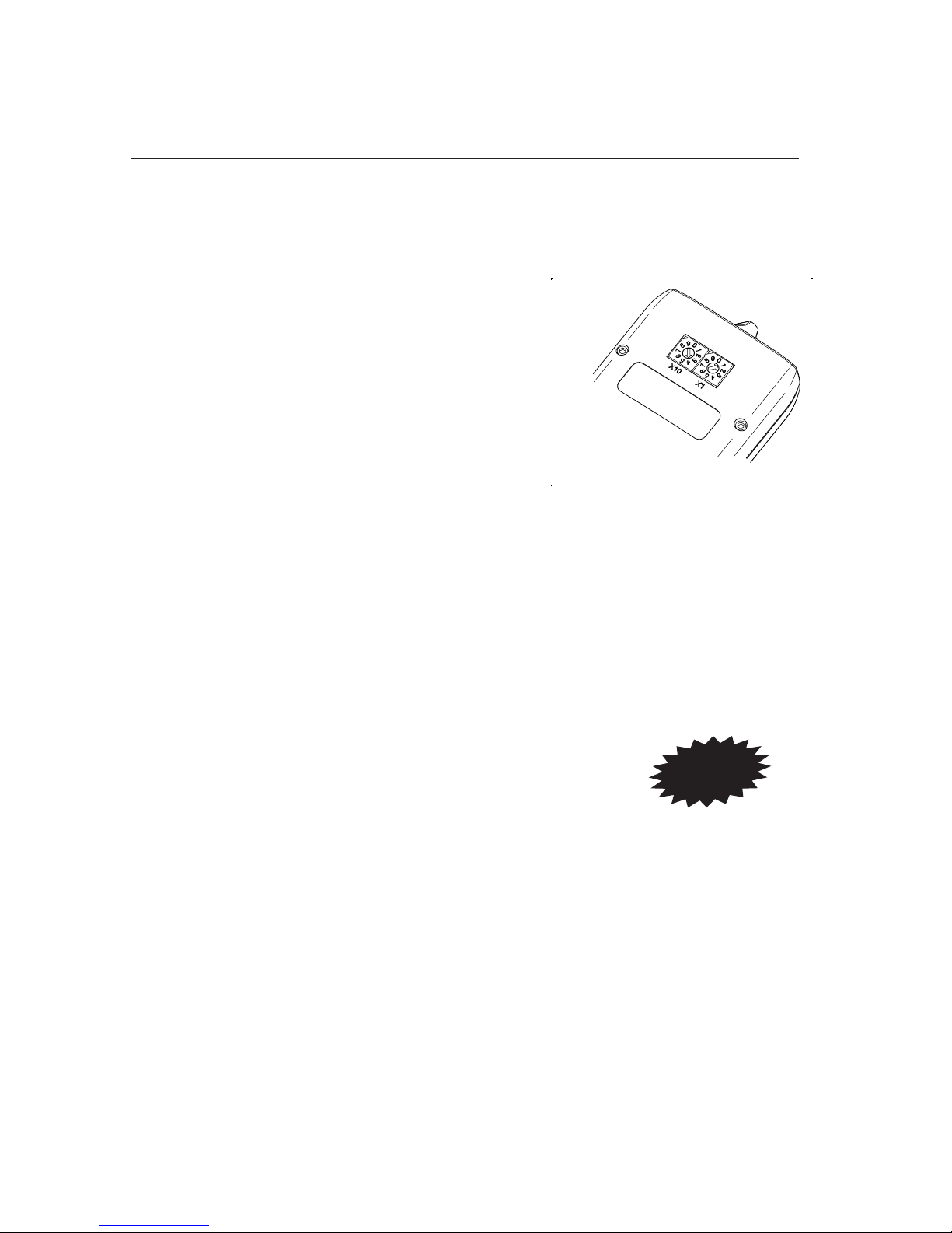
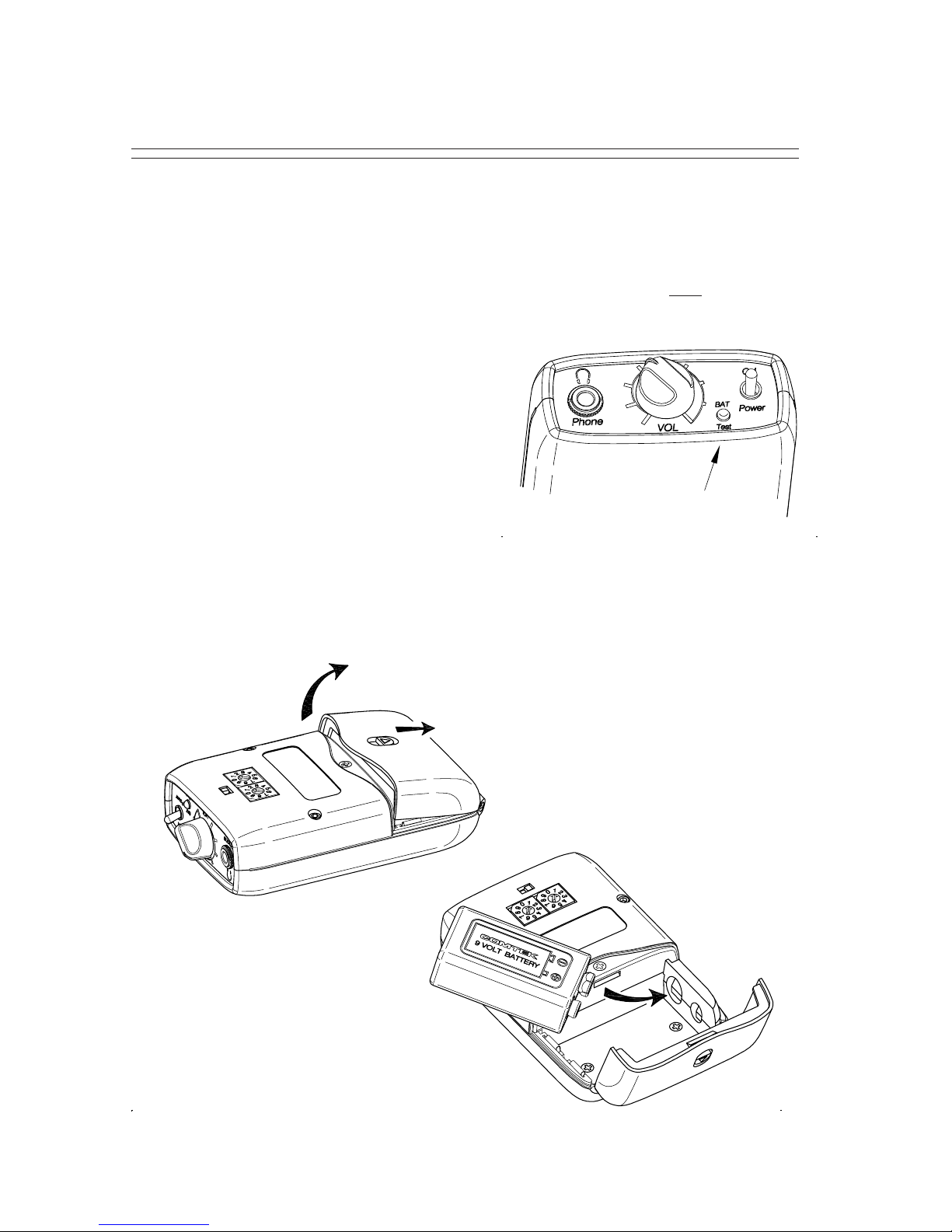
After you have determined the channel on which you are going to operate,
position the two rotary switches to indicate the channel. The left rotary
switch is for tens and the right rotary switch is for ones. To select channel 41
(216.0250 MHz), position the left rotary switch to point to 4 (X10), and
position the right rotary switch to point to 1 (X1). Refer to frequency charts
on pages 5 and 6 for selectable frequencies.
Multiple Channel Operation
Simultaneous operation of more than two channels
requires frequency coordination to avoid intermodulation
interference. This interference could result in poor or unusable performance.
When multiple transmitters are broadcasting, the RF signals will “mix”
together generating additional signals. If these product frequencies are
too close to a frequency which you are using, you will experience this
type of interference. This condition is common to all radio receivers to some
extent. This interference produces whistle and whine type sounds
and/or reductions of range. Toavoid this typeof interference, you should
selectfrequencies from oneof the standardgroups (see frequency group
chartson page 5),oryou can useCOMTEK’sfrequency selection guide
softwaretodetermineappropriate frequencies. Contact COMTEK to
obtain a free copy of the frequency selection software or download it off
the web at www.comtek.com/support.html
IMPORTANT