David White L6-20N Manuale utente

L6-20N Level and
LT6-900N Level-Transit
10
60
70
80
90
80
70
60
20
20
10
10
10
10
20
20
30
30
40
40
50
50
60
60
70
80
90
80
70
60
50
40
30
20
10
50
5
0
30
3
40
4
4
50
5
50
50
10
20
30
40
50
60
70
80
90
80
70
60
50
50
40
40
30
30
20
20
10
10
20
20
30
30
40
40
50
50
60
60
70
80
90
80
70
60
50
40
30
20
10
L6-20N Level (Model 44-8824)
LT6-900N Level-Transit (Model 44-8834)
For customer service, call (815) 432-9200
L6-20N / LT6-900N Owner's Guide
00-8830-810

With David White
your sights are set
on precision and accuracy.
Congratulations! You’ve purchased a David White builder/contractor
instrument, American-made and known throughout the world for
precision and accuracy.
The purpose of this booklet is to acquaint you with the instrument,
its components, proper care and handling.
Our levels and level-transits are constructed to withstand
extremely rugged field use. Like all precision instruments,
however, they should be treated with reasonable care to
prolong life and accuracy.
Quality and innovation since 1900.
All instruments are adjusted when they are shipped from the
factory. It is the customer’s responsibility to check and to ensure
instruments are adjusted prior to using.
David White is not responsible for errors caused by instruments
that are out of adjustment.
Contact your distributor, dealer or David White for
information on the nearest facility to check if your instrument
is properly adjusted. Some customers may choose to check
the instrument themselves. This can be done by following
the “Checking for Calibration” instructions at the back of this
manual. All actual adjustments must be done by a qualified
service facility.
All specifications are subject to change without notice.

Specifications
Meridian L6-20N Level
Meridian LT6-900N Level-Transit
Optimum sighting range: Recommended job range up to 200 feet.
Accuracy range:
Recommended for jobs requiring accuracy within
1/4"
at 75 feet.
TELESCOPE
Power 22X
Length 10.5" (26.5cm)
Minimum Focus 4 ft. (1.2m)
Aperture .75" (19mm)
Field of View 2' @ 100' (.6m @ 30m)
No. of Lenses 6
HORIZONTAL CIRCLE
Graduation Diameter 3.62" (92mm)
Graduations Each 1°
Numbers Each 10°, 0-90-0°
Vernier Double direct to 15 min.
VERTICAL ARC (LT6-900N only)
Graduations Each 1°
Numbers Each 10°, 45-0-45°
CENTER Planar bearing
LEVEL VIAL 10 min. per 2mm
WEIGHT L6-20N LT6-900N
Instrument only 3.25 lbs. (1.5kg) 4.5 lbs. (2.0kg)
Instrument, case,
3 oz. plumb bob 6 lbs. 6 oz. (3kg) 7 lbs. 10 oz. (4kg)
CASE Double-walled polyethylene
TRIPOD 5/8 x 11 JIS
2

General Description
Meridian L6-20N Level
Meridian LT6-900N Level-Transit
10
20
30
40
50
60
70
80
90
80
70
60
50
50
40
40
30
30
20
20
10
10
20
20
30
30
40
40
50
50
60
60
70
80
90
80
70
60
50
40
30
20
10
10
60
70
80
90
80
70
60
20
20
10
10
10
10
20
20
30
30
40
40
50
50
60
60
70
80
90
80
70
60
50
40
30
20
10
50
5
0
30
3
40
4
4
50
5
50
50
1. Telescope objective lens 9. Telescope lock lever
2. Eyepiece 10. Vertical arc
3. Focusing knobs 11. Vertical arc pointer
4. Instrument level vial 12. Vertical clamp
5. Horizontal graduated circle 13. Vertical tangent
6. Horizontal vernier 14. Three leveling screws
7. Horizontal clamp 15. 5/8 x 11 JIS threaded base
8. Horizontal tangent
1.
1.
5.
5.
6.
6.
10.
14.
14.
15.
15.
11.
2.
7.
8.
9.
8.
7.
3.
4.
4.
2.
3. 12. 13.
3

The telescope provides a sharp image magnified 22 times. This means the
object sighted appears 22 times closer than it would with the naked eye.
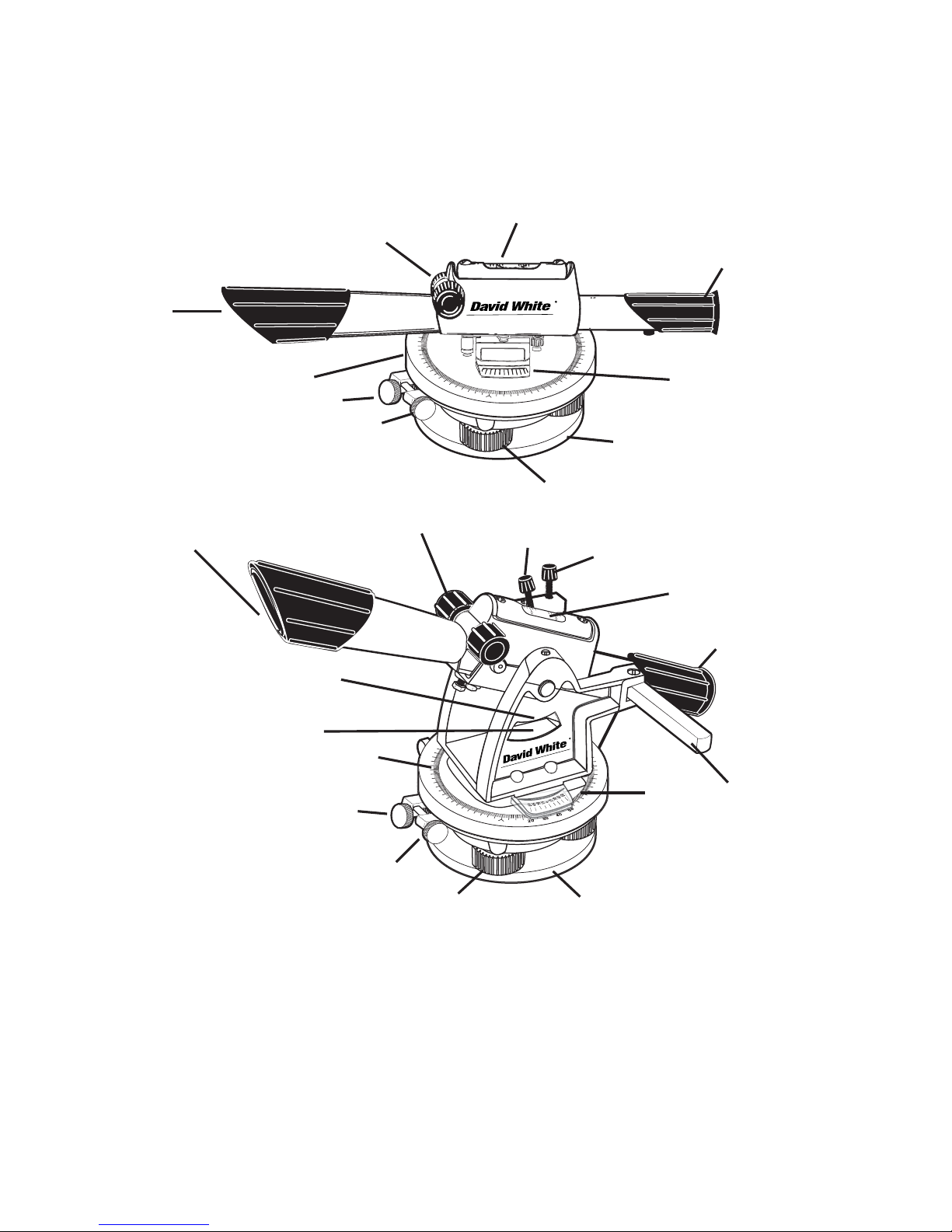
The telescope features a built-in sunshade which protects the objective
lens (1) and reduces glare.
To focus on an object, sight through the eyepiece (2) and turn the focus-
ing knobs (3) with either right or left hand. Cross hairs are in constant
focus. All focusing is internal. The telescope does not move outward or
inward as objects are focused. David White Meridian instruments use the
smooth precision of a rack and pinion mechanism for focusing. Focus
range is from four feet to infinity. For closer focus, turn the knob clockwise.
For farther focusing, turn counterclockwise.
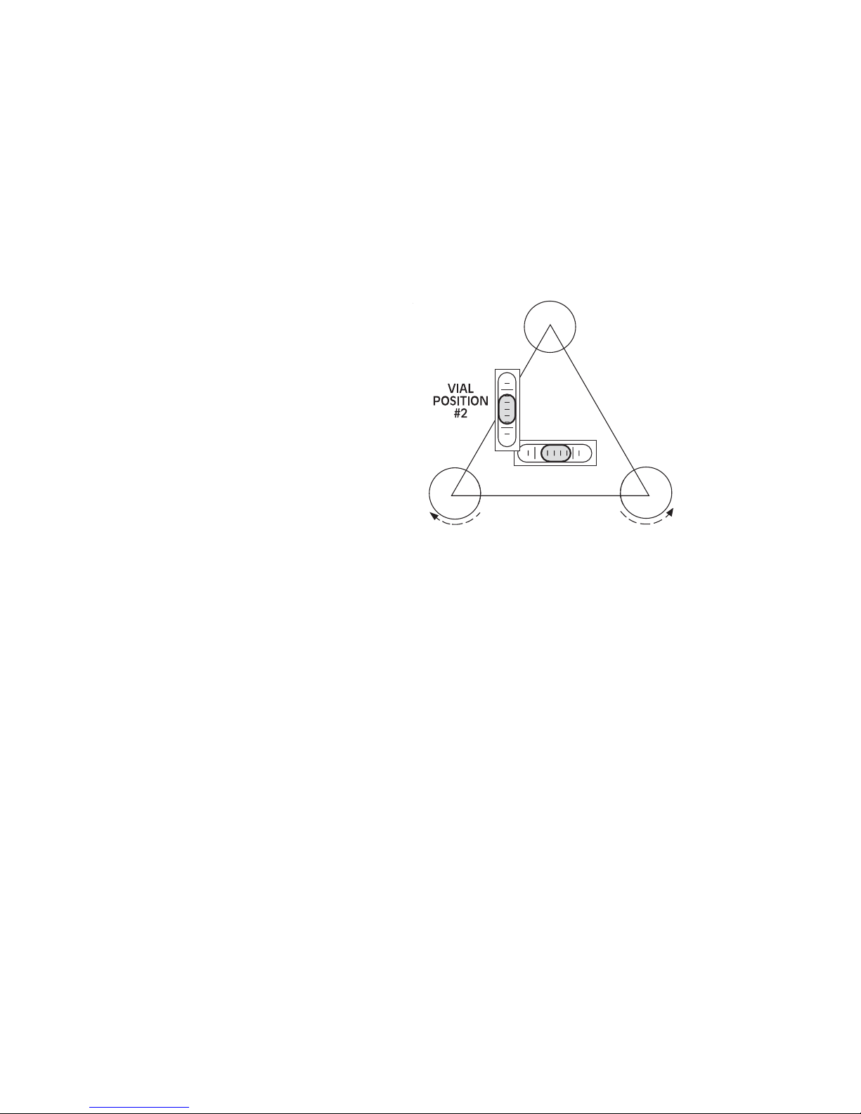
The instrument leveling vial (4) is protected by a strong, die-cast casing,
and is graduated to facilitate centering the bubble.
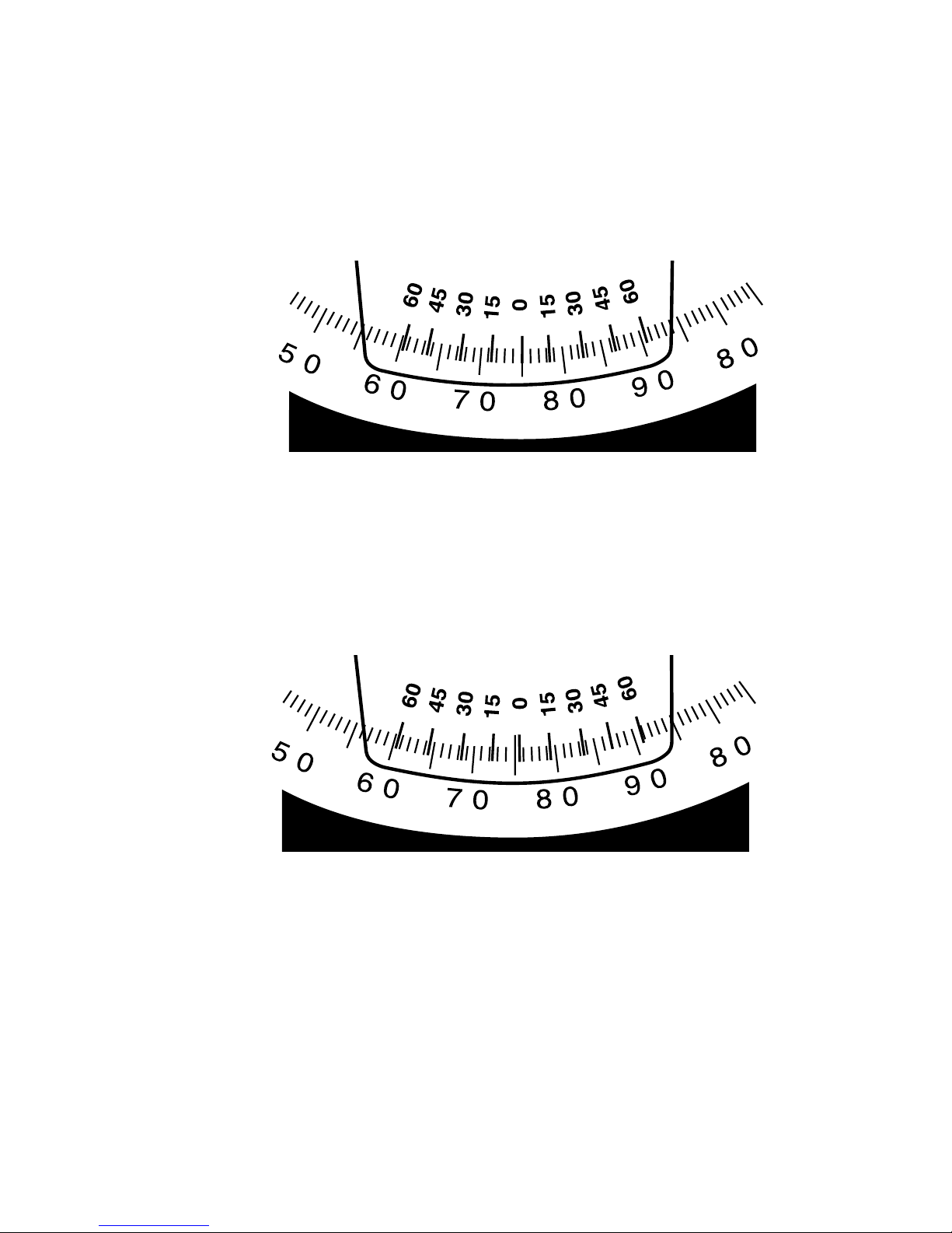
The horizontal circle (5) can be rotated for easy angle setting and read-
ing and is divided in quadrants (0-90°). The circle is marked by degrees
and numbered every 10 degrees.
The horizontal vernier (6) permits dividing whole degrees into fractions of
1/4° (15 minutes). See page 9 for circle and vernier reading instructions.
Approximate horizontal sightings are held firmly in place by means of a
clamp (7). Then, precise horizontal settings can be made with the tangent
(8). The clamp must be hand tightened in order for the tangent to function.
(THE FOLLOWING INDENTED PARAGRAPHS APPLY TO THE LT6-900N
LEVEL-TRANSIT ONLY.)
The Meridian Level-Transit is a combination instrument. Its tele-
scope moves up and down 45 degrees, and rotates 360 degrees, to
measure vertical and horizontal angles.
The telescope lock lever (9) must be in a closed position when
the instrument is to be used as a level; open when used as a
transit for vertical sightings. It is shown in the open position.
The vertical arc (10) is divided in degrees and numbered every 10
degrees up to 45 degrees, for both upward and downward angles,
and has an adjustable index pointer (11).
The vertical clamp (12) holds the telescope at a vertical angle.
Fine vertical settings can be made with the vertical tangent (13).
The vertical clamp must be hand tightened before the tangent will
function.
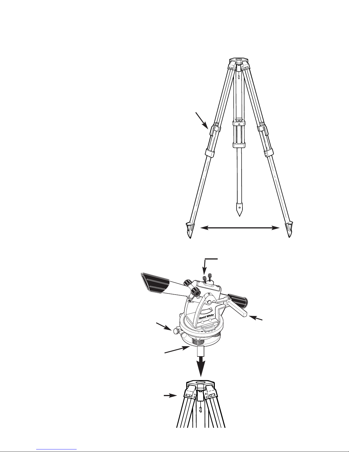
Both the L6-20N and LT6-900N have three leveling screws (14) for level-
ing the instrument. The instrument is mounted to the tripod by screwing the
tripod stud into the 5/8 x 11 JIS threaded base (15).
4

Setting up your instrument
Each of the following steps is
important in preparing to use your
instrument.
1. These instruments must be
used with a 5/8 x 11 JIS thread
tripod. For easiest setup and best
operating results, it is recommend-
ed that the David White tripod is
used. It is important that the tripod
is set up firmly. Make sure that the
tripod points are well into the
ground.
When setting up on a smooth floor
or paved surface, secure the points
of the legs by chipping the con-
crete, attaching chains between the
legs, or putting a brick in front of
each leg. If setting up in dirt, apply
your full weight to each leg to pre-
vent settlement.
Check the tripod legs. They should
have about a 3 foot spread, posi-
tioned so the top of the tripod
head appears level.
If using a tripod with
adjustable legs, be
sure the leg levers are
securely tight-
ened.
10
60
70
80
90
80
70
60
20
20
10
10
10
10
20
20
30
30
40
40
50
50
60
60
70
80
90
80
70
60
50
40
30
20
10
50
5
0
30
3
40
4
4
50
5
50
50
1. Loosen clamp
3. Three
screw
leveling
4. Hand tighten
tripod mounting
stud
1A. Loosen
clamp 2.Close lock
lever
5
3 feet
Lift
lever to
release
leg.

2. Before setting up your instrument, loosen the clamps. If using
the level-transit, be sure the telescope lock lever is in the closed
position. Attach the instrument to the tripod securely, hand tight-
ening the tripod mounting stud to the instrument base. If setting
up over an exact point, read step 3; otherwise, continue to step 4.
3. If setting up over a point, use a plumb bob to center on the
exact point. To hang the plumb bob, attach cord to the plumb bob
hook on the screwdriver-style handle of the tripod. Knot the cord
as illustrated.
Move the tripod and instrument over the approximate point. (Be
sure the tripod is set up firmly again, as described in step 1.) Shift
the instrument on the tripod head until the plumb bob is directly
over the point. Then set the instrument leveling screws as
described in step 4.
Hanging the
plumb bob.
To hang the plumb
bob, attach cord to
the plumb bob
hook on the tripod
and knot the cord
as illustrated.
6
1. Move tripod and
instrument over the
approximate point.
2. Shift the instrument
to line up plumb bob
exactly.

4. LEVELING THE THREE SCREW INSTRUMENT
Instruments utilizing three leveling screws are mounted on the tri-
pod and leveled in the following manner:
Mount the instrument on the tripod. Lock the telescope in place
with the lock lever and line up the telescope vial in position #1 as
shown (Fig. 2). Then grasp screws A & B so that both thumbs are
moving in opposite directions, either toward each other or away
from each other. Note that the bubble moves in the same direc-
tion as your left thumb. Do not permit the screws to come com-
pletely out of their bushings.
Keep about half the length
engaged. When the bubble
is centered in position #1,
turn the instrument and
observe the vial in position
#2. Now center the bubble in
position #2 using only screw
C.
Your David White Instrument
should now be leveled up,
but to be certain, double-
check. Rotate the instrument 180° so the vial is reversed. If the
bubble will not center when reversed, follow adjustment procedure
outlined under "Bubble Adjustments."
NOTE: Bubble adjustments must be correct if proper results are to
be obtained using the instrument.
7
AB
C
VIAL
POSITION
#1

BUBBLE ADJUSTMENTS
If the telescope bubble does not remain centered after having lev-
eled the instrument, and reversed the telescope end for end (180°)
(as described under the chapters entitled “Leveling
the...Instrument”) the need for adjustment is indicated. Use a
screwdriver. .
With an adjusting screw "A" facing to the right of the bubble and
with telescope directly in line with two of the three leveling screws,
note to which side the bubble is off. If to the left, loosen screw "B"
very slightly to remove ONE-HALF the error. Remove the other
half of the error with the two level screws in line with the tele-
scope. If the bubble is still not exactly centered, repeat the proce-
dure.
If bubble is off to the right, tighten screw "A". Otherwise, the proce-
dure is identical (Fig. 3).
8
A
BC

Reading the circle and vernier
The 360° horizontal circle is divided in quadrants (0-90°). The
circle is marked by degrees and numbered every 10 degrees. To
obtain degree readings, it is only necessary to read the exact
degree at the intersection of the zero index mark on the vernier
and the degree mark on the circle (or on the vertical arc of the
level-transit.)
For more precise readings, the vernier scale is used. The vernier
lets you subdivide each whole degree on the circle into fractions,
or minutes. There are 60 minutes in a degree. If the vernier zero
does not coincide exactly with a degree mark on the circle, note
the last degree mark passed and, reading up the vernier scale,
locate a vernier mark that coincides with a circle mark. This will
indicate your reading in degrees and minutes.
Sighting and focusing
the telescope
Aim the telescope at the object and sight first along the top of the
telescope tube. Then look through the telescope and adjust the
focus.
When cross hairs are positioned on or near the target, tighten the
horizontal clamp and make final settings with the tangent to bring
the cross hair exactly on point.
9
75 degrees,
45 minutes
75 degrees
Questo manuale è adatto per i seguenti modelli
1
Indice
Altri manuali David White Livello laser


