DEC VT1000 Manuale utente

VT1000/VT1200
andDECimage1200
ServiceGuide
Order Number EK–V1000–SV.002
Digital Equipment Corporation

First Edition, September 1990
Second Edition, April 1991
The information in this document is subject to change without notice and should not
be construed as a commitment by Digital Equipment Corporation. Digital Equipment
Corporation assumes no responsibility for any errors that may appear in this document.
The software described in this document is furnished under a license and may be used or
copied only in accordance with the terms of such license.
No responsibility is assumed for the use or reliability of software on equipment that is not
supplied by Digital Equipment Corporation or its affiliated companies.
Restricted Rights: Use, duplication, or disclosure by the U. S. Government is subject to
restrictions as set forth in subparagraph (c) (1) (ii) of the Rights in Technical Data and
Computer Software clause at DFARS 252.227–7013.
Copyright © Digital Equipment Corporation 1990, 1991
All Rights Reserved.
Printed in U.S.A.
The following are trademarks of Digital Equipment Corporation:
DEC, DECimage 1200, DECnet, DECterm, DECwindows, ThinWire, ULTRIX, VAX, VMS,
VR150, VT, VT1000, VT1200, and the DIGITAL logo.
UNIX is a trademark of American Telephone and Telegraph Company.
This document was prepared and published by Educational Services Development and
Publishing, Digital Equipment Corporation.

Contents
About This Guide vii
1 Overview of the Terminal
1.1 The Video Terminal’s Components ..................... 2
1.1.1 System Box .................................... 3
1.1.2 Monitor ....................................... 6
1.1.3 Keyboard ...................................... 7
1.1.4 Mouse ........................................ 7
1.2 Operating Features ................................ 7
1.2.1 X Window Sessions and Video Terminal Sessions ....... 7
1.2.2 Network Communication Protocols . . . ............... 7
1.2.3 Customizing the Terminal . ........................ 8
1.2.4 Overriding Passwords ............................ 8
1.3 Site Requirements . ................................ 8
2 Testing
2.1 Terminal Self-Tests ................................ 10
2.1.1 Successful Power-Up Self-Tests ..................... 11
2.1.2 Menu-Driven Diagnostic Tests ...................... 14
2.1.3 Displaying Video Alignment Patterns . ............... 20
2.2 Running Remote Diagnostic Tests over the Network (VMS
Systems) ........................................ 21
2.2.1 NCP Testing .................................... 22
2.2.2 LANSA Testing . ................................ 26
2.3 Testing the LAT . . . ................................ 29
2.4 Testing on ULTRIX and UNIX Systems . . ............... 30
2.4.1 Testing TELNET ................................ 30
2.4.2 Using ping ..................................... 33
iii

iv Contents
3 Troubleshooting
3.1 Identifying the Terminal’s Configuration . ............... 35
3.2 Troubleshooting by Flowchart ........................ 36
3.3 Troubleshooting by Error Code........................ 38
3.3.1 Screen Error Messages............................ 40
3.3.2 Reading LED Error Codes . ........................ 42
3.4 Troubleshooting General Problems..................... 44
4 Removing and Replacing FRUs
4.1 Cover . . . ........................................ 51
4.2 RAM Controller Board (VT1000 / VT1200 Only) . . . ....... 52
4.3 Image Board (DECimage 1200 Only) ................... 53
4.4 SIMM Cards ..................................... 54
4.5 ROM Board ...................................... 56
4.6 System Logic Board ................................ 57
4.7 Power Supply ..................................... 59
4.8 Fan ............................................ 60
4.9 Keyboard, Mouse, and Printer ........................ 61
5 Starting a Session
5.1 Before You Start—Required Information . ............... 62
5.2 Starting a Session on a VMS System ................... 63
5.3 Starting a Session on an ULTRIX or UNIX System . ....... 66
5.4 Ending a Session . . ................................ 68
5.5 Using Secure Reset ................................ 69
5.6 Displaying the Customize Image Dialog Box (DECimage
1200 Only) ....................................... 71
A Related Documents

Contents v
B Recommended Spares List
Figures
2–1 Terminal Manager Window . . ........................ 12
3–1 Terminal Troubleshooting Flowchart ................... 37
Tables
2–1 Level 0 Tests ..................................... 11
2–2 Level 1 Tests ..................................... 13
2–3 Diagnostics Dialog Box Buttons ....................... 19
2–4 NCP Tests ....................................... 23
2–5 P3 Values to Specify Mode Bits ....................... 24
3–1 Troubleshooting by Error Code........................ 38
3–2 Troubleshooting Error Code 13 ....................... 39
3–3 Level 0 Screen Error Messages ....................... 40
3–4 Level 1 and Menu-Driven Screen Error Messages . . ....... 41
3–5 LED Error Reporting Method ........................ 42
3–6 Troubleshooting the Terminal ........................ 44
A–1 Related Documents ................................ 73


AboutThisGuide
This guide describes how to service the VT1000 video terminal, the
VT1200 video terminal, and the DECimage 1200 video terminal. The
guide uses the generic term terminal when describing information
common to all three products.
Audience
The guide is for Digital’s Customer Services Engineers and qualified
self-maintenance customers.
Organization
The guide has five chapters that cover the following topics:
Terminal overview
Testing the terminal
Troubleshooting the terminal
Removing and replacing field replaceable units (FRUs)
Starting a session on the terminal
Appendices provide information on the following topics:
Modems, cables, and related documentation
Recommended spares
Tools and Equipment
You need the following tools to service the terminal:
vii

viii About This Guide
Tools and Equipment Part
Number
Phillips screwdriver, number 2 29-11005-00
Wrist strap and antistatic mat
(included in Customer Services antistatic kit) 29-26246-00
Two 6-pin, DEC-423 loopback connectors (modular jack) 12-25083-01
Mouse loopback connector 12-25628-01
Two Ethernet terminators (H8225-00) 12-26318-01
ThinWire Ethernet T-connector (H8223-00) 12-25869-01
Tools required for VR150, VR262, VR315, VR319, and VRE01
monitors (See the service documentation for each monitor.)
Conventions
The following conventions are used in this guide:
Convention Meaning
terminal Refers to the VT1000 terminal, the VT1200
terminal, and the DECimage 1200 terminal.
mouse Refers to any pointing device, such as a mouse, a
puck, or a stylus.
MB1, MB2, and MB3 MB1 indicates the left mouse button. MB2 indicates
the middle mouse button. MB3 indicates the right
mouse button. (The buttons can be redefined by the
user.)
Keyboard key Keys or switches that are labeled appear in a box.
Example: Press the Return key.
Ctrl
key
For Ctrl key sequences, hold down Ctrl and press the
other key.
Cautions Provide information to prevent damage to
equipment or software.
Notes Provide general information about the current topic.
PN This is an abbreviation for part number.

1
OverviewoftheTerminal
1
This chapter provides an overview of the terminal’s hardware and
connectors, operating features, and site requirements.
You can use the terminal to:
• Connect to an Ethernet network through the terminal’s ThinWire
port.
• Connect directly to a computer through one of the terminal’s two
serial ports, like a traditional terminal.
• Display multiple video terminal (VTE) windows and applications over
both the Ethernet and serial lines at the same time.
• Interact over an Ethernet network with multiple VTE window,
DECwindows, and X window applications running under the VMS,
ULTRIX, or UNIX operating system.
• Support the local area terminal (LAT) protocol for VMS systems
and the transmission control protocol/Internet protocol (TCP/IP) for
ULTRIX and UNIX systems.
NOTE
To identify the terminal’s hardware configuration, see Section 3.1.
1
2 Overview of the Terminal
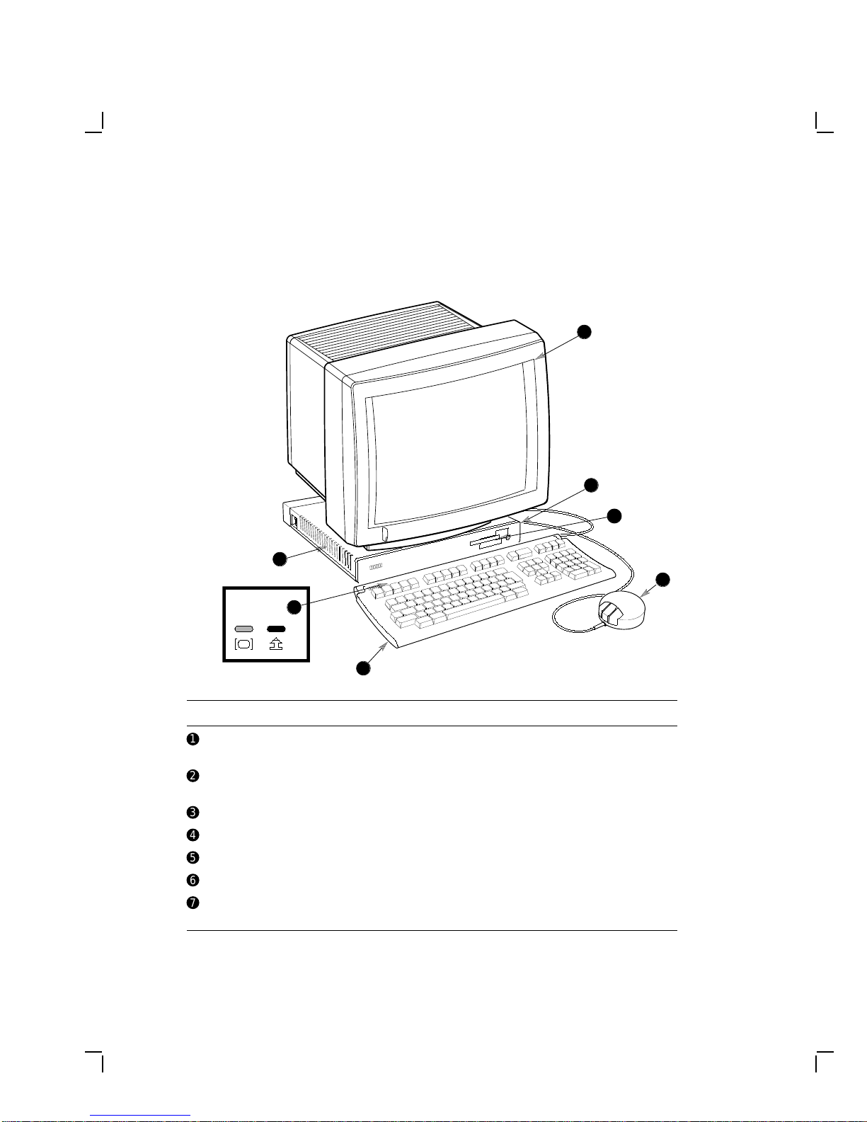
1.1 The Video Terminal’s Components
The video terminal includes the following components:
MA-0509-90.DG
Keyboard
LEDs
7
6
5
4
3
2
1
Item Name Description
!
Monitor VR150, VR262, VR315, VR319, or VRE01
electroluminescent (EL) flat panel
"
System board LED Red LED, visible through the ventilation slots
on the side of the system box
#
Terminal logo VT1000, VT1200, or DECimage 1200
$
Mouse —
%
Keyboard LK400 series
&
Keyboard LEDs Hold and lock indicators
'
Power supply LED Green LED, visible through the ventilation slots
on the side of the system box
Questo manuale è adatto per i seguenti modelli
2
Indice
Altri manuali DEC Terminale touch


