digitalview HD-3000v2 Manuale utente

Specifications subject to change without notice
© Digital View Ltd – Doc Ver 1.00: 23 Feb, 2023 Page 1 of 16
HD/SD-SDI to HDMI adaptor board
HD-3000v2
Manual
Specifications subject to change without notice
© Digital View Ltd – Doc Ver 1.00: 22 Feb, 2023 Page 2 of 16
Table of Contents
1. Introduction
3
2. Connectors, Pin outs & Jumpers
5
3. LED status and Source switching
9
4. Board Dimensions
10
5. Signal Support Mode Table
11
6. Specification
12
7. Appendix I - RS-232 control protocols
13
8. Appendix II - System Connection with
Digital View LCD controllers
14
9. Warranty, Caution & Limitation of Liability, Trademarks
15
10. Contact details
16
11. Revision History
17
1. Introduction
Specifications subject to change without notice
© Digital View Ltd – Doc Ver 1.00: 23 Feb, 2023 Page 3 of 16
The HD-3000v2 provides a SD/HD-SDI signal front end to Digital View LCD controller boards.
HD-3000v2 Key Features
a. Converts SD/HD-SDI (SD, HD and 3G) video input to HDMI output, up to Full-HD resolution.
b. Re-clocked loop through outputs for “daisy chaining” multiple monitors or other equipment to the same HD-SDI source, includes
embedded audio.
c. Fully compliant with the SMPTE 259M-C, SMPTE 292M, SMPTE 424M, 425M standards.
d. Supports 1.5Gbits & 3Gbits bit rate input signal support. The mode support is listed in page 10.
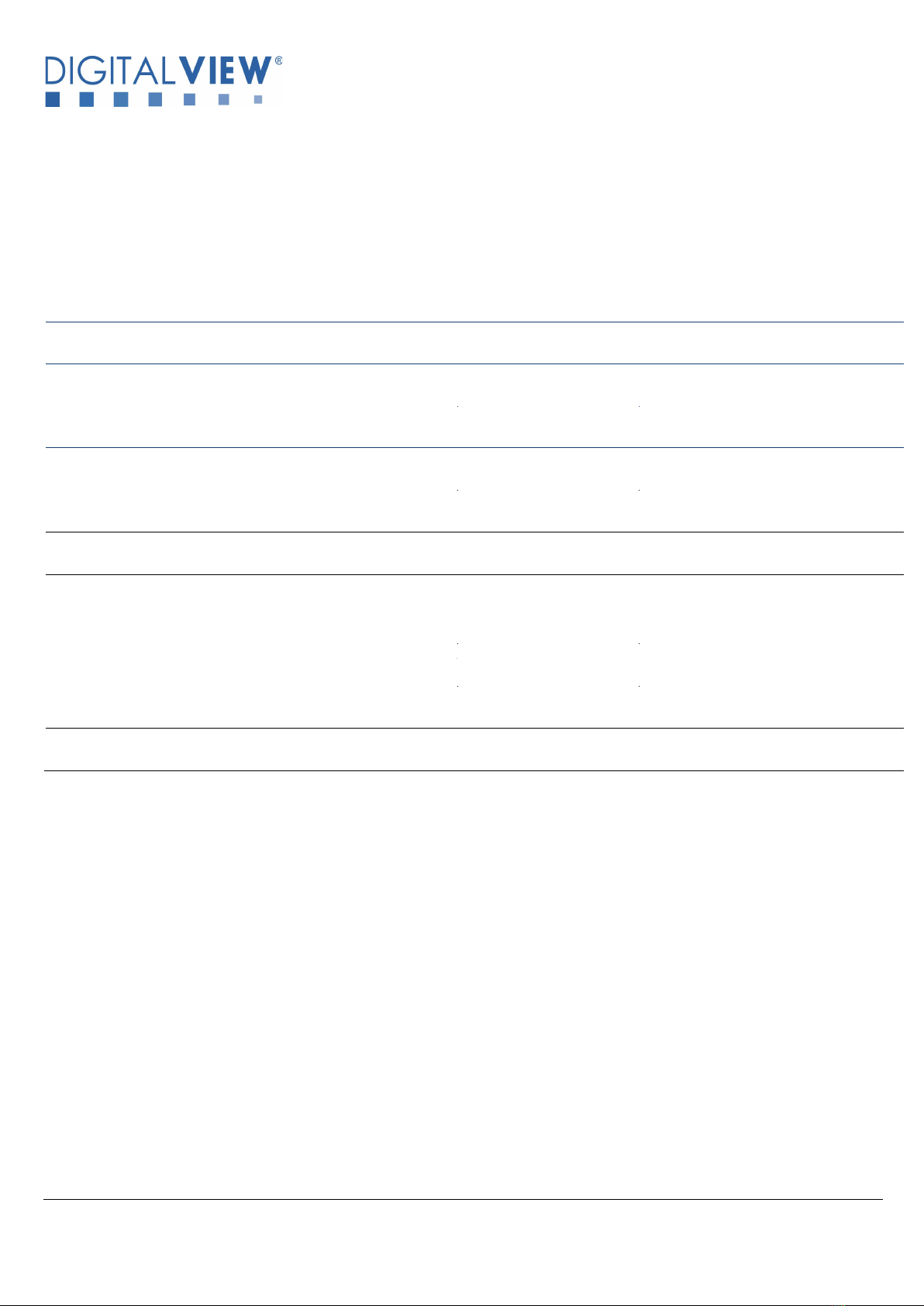
e. Two SDI input port switching with One HDMI out supported.
HD-3000v2 supports Path A (HD-SDI input from J1 port convert to output HDMI at HDMI1/HDMI1A port) or Path B (HD-SDI input
from J2 port convert to output HDMI at HDMI1/HDMI1A port). See Figure below :
f. HD-SDI re-clock loop through output. J1 HD-SDI input and re-clock loop through to J3 HD-SDI output. J2 HD-SDI input and re-clock
loop through to J4 HD-SDI output.
g. HDMI (v1.3) x 1 output port. One HDMI output ports are HDMI1/HDMI1A outputting 1920x1080p60 mode.
h. Stereo embedded audio support .
i. Input interlaced SDI video is de-interlaced to HDMI output for non-frame buffered DV controller.
g. Provide fast input port switching between the dual SDI inputs if the two SDI inputs are in the same video format. (HDMI output is
always ON).
h. PIP support option (custom firmware required).
Specifications subject to change without notice
© Digital View Ltd – Doc Ver 1.00: 22 Feb, 2023 Page 4 of 16
2. CONNECTORS, PINOUTS & JUMPERS
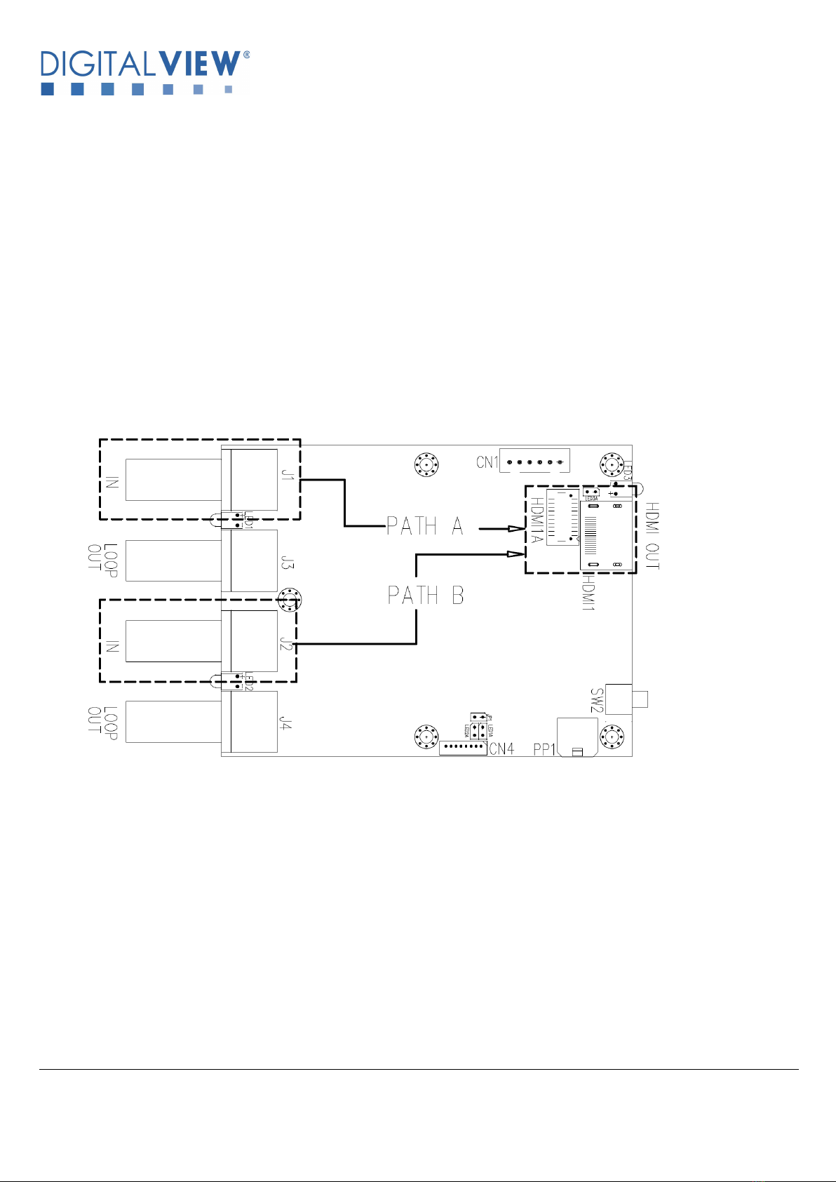
The various connectors are:
Summary: Connectors
Ref
Description
Type / Use
J1
SD/HD-SDI 1 Input
BNC connector
J2
SD/HD-SDI 2 Input
BNC connector
J3
SD/HD-SDI 1 re-clock loop through output
BNC connector
J4
SD/HD-SDI 2 re-clock loop through output
BNC connector
CN1
RS-232 & I2C control connector
JST 6-way, B6B-XH-A or compatible (Matching type : XHP-6)
> (Matching power & I2C cable P/N 426090700-3 for connection
with Digital View LCD controller)
> (Matching cable with DB9 female connector P/N 426090200-3
for RS-232 command communication)
> (Matching cable with DB9 male connector P/N 426090400-3 for
RS-232 command communication)
CN4
External I/O connector
Hirose DF13-8P-1.25DSA or compatible.
(Matching type : Hirose DF13-8S-1.25C)
(Matching extend cable with Hirose DF13-8S-1.25C
connector : P/N 426894500-3)
HDMI1
HDMI 1 Output
HDMI connector

Specifications subject to change without notice
© Digital View Ltd – Doc Ver 1.00: 23 Feb, 2023 Page 5 of 16
Ref
Description
Type / Use
HDMI1A
Alternate HDMI 1 Output
JST BM20B-SRDS (Matching type : JST SHDR-20V-S-B)
(Matching extend cable with female HDMI connector :
P/N 426301800-3)
(Matching extend cable with male HDMI connector :
P/N 426006600-3)
PP1
Power Input (Alternate)
Molex 43650-0200 compatible
(Matching connector type : Molex 43645-0200 compatible)
(Matching power cable : P/N 426013800-3)
SW2
Manual SDI 1 / SDI 2 Input port selection
(work for standalone application only)
Tact Switch
Summary: Jumper settings :
Ref
Purpose
Note
LED1A
External LED connection
Refer to pin assignment in page 7
LED2A
External LED connection
Refer to pin assignment in page 7
LED3A
External LED connection
Refer to pin assignment in page 7
JP1
Reserved for programming use
Reserved

Specifications subject to change without notice
© Digital View Ltd – Doc Ver 1.00: 22 Feb, 2023 Page 6 of 16
Summary : PinOuts :
CN1 – RS-232 & I2C control : JST B6B-XH-A (Matching type : XHP-6)
PIN
SYMBOL
DESCRIPTION
1
SCLK
I2C_SCLK
2
SDATA
I2C_SDATA
3
VCC
+5V (optional input power)
4
TXD
RS-232 Tx data
5
GND
Ground
6
RXD
RS-232 Rx data
CN4 – External I/O connector : Hirose DF13-8P-1.25DSA (Matching type : Hirose DF13-8S-1.25C)
PIN
SYMBOL
DESCRIPTION
1
3V3
3.3V output
2
LED3
LED3 Anode
3
N/A
N/A
4
N/A
N/A
5
EXT_IP_1
Reserved
6
LED1
LED1 Anode
7
LED2
LED2 Anode
8
GND
LED Cathode
LED1A, LED2A, LED3A – External LED connection
PIN
SYMBOL
DESCRIPTION
1
+
LED Anode
2
-
LED Cathode
HDMI1A – Alternate HDMI connector: JST BM20B-SRDS (Matching type : JST SHDR-20V-S-B)
PIN
SYMBOL
DESCRIPTION
1
GND
Ground
2
GND
Ground
3
RXC+
TMDS Data C+
4
RXC-
TMDS Data C-
5
RX0+
TMDS Data 0+
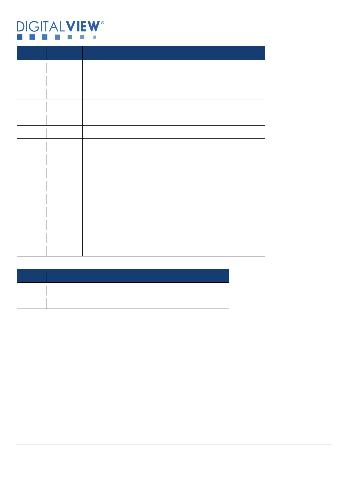
Specifications subject to change without notice
© Digital View Ltd – Doc Ver 1.00: 23 Feb, 2023 Page 7 of 16
PIN
SYMBOL
DESCRIPTION
6
RX0-
TMDS Data 0-
7
RX1+
TMDS Data 1+
8
RX1-
TMDS Data 1-
9
RX2+
TMDS Data 2+
10
RX2-
TMDS Data 2-
11
GND
Ground
12
GND
Ground
13
MSTR2_SCL
Reserved
14
MSTR2_SDA
Reserved
15
DDC_5V
+5V power supply for DDC (optional)
16
HPD
Hot plug detection
17
DDC_SCL
DDC serial clock
18
DDC_SDA
DDC Data
19
VCC1
VCC 5V output
20
VCC2
VCC 5V output
PP1 - 12VDC power supply
PIN
DESCRIPTION
1
+12VDC in
2
Ground

Specifications subject to change without notice
© Digital View Ltd – Doc Ver 1.00: 22 Feb, 2023 Page 8 of 16
3. LED status and Source switching
Status LEDs on board, definition: LED1, LED2, LED3
Ref
Description
LED1 / LED2
Green LED on: Signal detected
LED3
Green LED on: Power on and HDMI output
Source switching:
The two SDI inputs can be selected by:
a) On board tact switch to toggle from one SDI input to another one SDI input:
* Tact switch functionality will be disabled when connected with a Digital View LCD controller as in (c) below.
b) RS-232 commands (Refer to Appendix I)
c) Connect with Digital View LCD controller (Refer to Appendix II)
The last selected SDI input source will be memorized after power cycle.

Specifications subject to change without notice
© Digital View Ltd – Doc Ver 1.00: 23 Feb, 2023 Page 9 of 16
4. BOARD DIMENSIONS
Ready-made 3D Pro-E (SLDPRT) drawing files - Save time and effort for your system volumetric analysis design.
Includes jpg file previews. Please go to download at http://www.digitalview.com/accessories/hd-3000v2
The maximum thickness of the adaptor board is 18mm (measured from bottom of PCB to top of components, excluding the
BNC connectors. We recommend clearances of:
• 5mm from bottom of PCB - if mounting on a metal plate we also recommend a layer of suitable insulation material is
added to the mounting plate surface.
• 10mm above the components
• 3~5mm around the edges
Any of the holes shown above can be used for mounting the PCB, they are 3.2mm in diameter.
CAUTION: Ensure adequate insulation is provided for all areas of the PCB with special attention to high voltage parts
such as the inverter.
Specifications subject to change without notice
© Digital View Ltd – Doc Ver 1.00: 22 Feb, 2023 Page 10 of 16
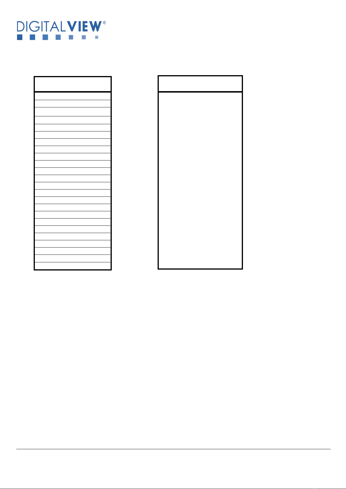
5. SIGNAL SUPPORT MODE TABLE
HDMI output mode
1920x1080p60
(for input fast port switching)
SDI input Mode
576i50 (PAL)
480i60 (NTSC)
720p60 (4:2:2)
720p59.94 (4:2:2)
720p50 (4:2:2)
720p30 (4:2:2)
720p29.97 (4:2:2)
720p25 (4:2:2)
720p24 (4:2:2)
720p23.98 (4:2:2)
1080p30 (4:2:2)
1080p29.97 (4:2:2)
1080p25 (4:2:2)
1080p24 (4:2:2)
1080p23.98 (4:2:2)
1080psf30 (4:2:2)
1080psf25 (4:2:2)
1080psf24 (4:2:2)
1080psf23.98 (4:2:2)
1080i60 (4:2:2)
1080i59.94 (4:2:2)
1080i50 (4:2:2)
1080p60 (4:2:2)
1080p50 (4:2:2)
Indice
Altri manuali digitalview Hardware per computer

Manuali Hardware per computer popolari di altre marche

EMC2
EMC2 VNX Series Manuale del proprietario

Panasonic
Panasonic DV0PM20105 Manuale utente

Mitsubishi Electric
Mitsubishi Electric Q81BD-J61BT11 Manuale utente

Gigabyte
Gigabyte B660M DS3H AX DDR4 Manuale utente

Raidon
Raidon iT2300 Manuale utente

National Instruments
National Instruments PXI-8186 Manuale utente


