
Dru Passo RCH Manuale utente
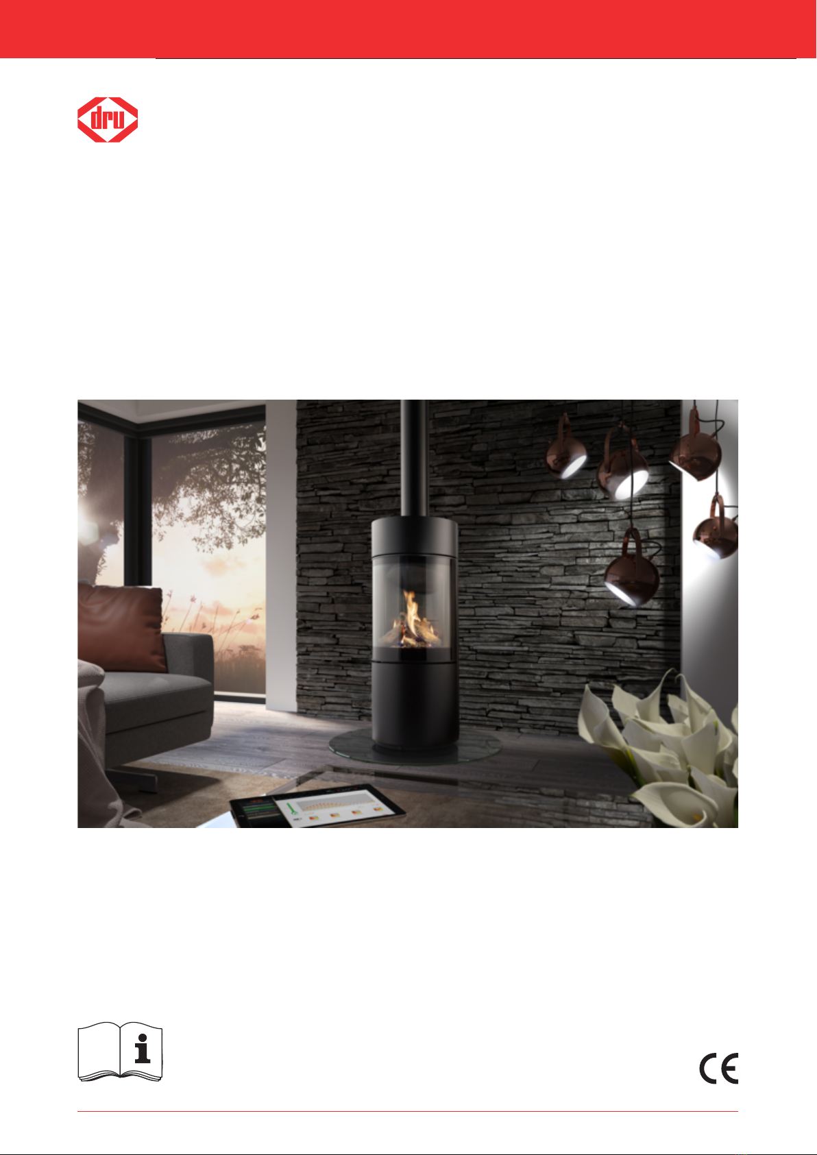
Installation manual
Passo RCH
G20/G25/G25.3 (Natural gas)
English
Store this document in a safe place
959.119.00 ENDRU-842422-EN-US-0420-5

Installation manual
2
1. Step-by-step installation plan 4
2. Introduction 5
3. CE declaration 5
4. Technical data 6
5. SAFETY 7
5.1 General 7
5.2 Regulations 7
5.3 Safety instructions 7
6. Preparation 8
6.1 Unpacking 8
6.2 Type of gas 8
6.2.1 Gas type conversion 8
6.3 Gas connection 8
6.3.1 Gas hose for gas connection 9
6.4 Electric connection 9
6.5 Components appliance control 10
7. Installation 11
7.1 Placing the appliance 11
7.3 Concentric system 15
7.3.1 General 15
7.3.2 Roof terminal (C31) 17
7.3.3 Wall terminal (C11) 20
7.3.4 Connection to an existing chimney 23
7.4 Connecting the appliance control 24
8. Appliance 26
8.1 Glass pane 26
8.1.1 Opening the glass pane 26
8.1.2 Closing the glass pane 27
8.2 Adjusting the appliance 28
8.3 Wood set 29
8.3.1 Placing the wood set 29
9. Control/operation 35
9.1 Principle of ignition cycle 36
9.2 Connecting the switch contact 36
9.3 Connection extra power supply (max. 80W, 230VAC) 37
9.4 Remote controls 37
9.4.1 Black remote control for the user 37
9.4.2 Orange remote control for the installer 37
9.5 Alternative operation 37
9.5.1 Wired 38
9.5.2 Wireless 39
9.5.2.1 Connection via ‘modbus’ protocol 39
9.5.2.2 Control via application 39
10. Final check 40
Content

Installation manual
3
10.1 Gas tightness 40
10.2 Gas pressure/line-pressure 40
10.3 Ignition main burner 40
10.3.1 First ignition of the appliance after installation or adjustments 40
10.3.2 Procedure for igniting the main burner 41
10.4 Flame picture 41
11. Delivery 42
12. Maintenance 43
12.1 Parts 43
Appendix 1: Malfunctions 44

1. Step-by-step installation plan
The major steps of the installation are described below,
Perform these steps and tick them once they have been performed correctly.
3Carefully read the installation manual before installing the appliance.
Installation manual
4
The appliance is now (after the above-mentioned steps) ready for use and the consumer is familiar with the possibilities
for using the appliance.
Check that the gas type and gas pressure is correct on the location where the appliance is placed.
Check that the supplied parts are present (see table 6-1).
Check the appliance for damages.
Make sure that the total installation complies with the applicable national, local and architectural regulations.
Make sure that there is a gas tap present that is always accessible and meets the legal regulations.
Ensure that the placement meets the applicable requirements concerning fire safety.
Make sure that the configuration of the concentric system with roof or wall duct corresponds with the imposed
requirements (see section 7.3).
Make sure the appliance control is connected correctly (see section 7.4).
Make sure that the restrictor slide and air inlet guides are correctly adjusted (see section 8.2).
Ensure a correctly placed wood, pebble set or broken glass set with accessories (see section 8.3).
Make sure the remote control is made ready for use (see section 9.4).
Check all gas connections for gas tightness (see section 10.1).
Make sure the appliance is safely ignited the first time (see section 10.3.1).
Ensure a cleaned glass pane in accordance with the instruction, before the atmospheric fire is ignited with the glass
pane for the first time (see chapter 12).
Check the appliance with installed glass pane for a correct ignition and a correct flame transfer of the main
burner(s) when igniting for the first time (see section 10/3/2).
Familiarise the user with the appliance (see chapter 11).
Check that the correct type of appliance has been delivered (see table 4-1).

2. Introduction
DRU, a manufacturer of gas-fired heating appliances, develops and produces products that comply with the highest
possible quality, performance and safety requirements. This appliance has a CE label, which means that it complies with
the essential requirements of the European Gas Appliance Directive. The appliance is supplied with an installation
manual and a user manual. Installation and maintenance of the appliance should be performed by a professional certified
expert with a proven knowledge and demonstrable competence in this field.
A professional expert takes all technical aspects such as heat output, gas connection and electricity into account, as well
as the flue gas discharge requirements. The information in this installation manual will ensure the appliance is installed in
such a way that it will function properly and safely. If the installation instruction is not clear, national/local regulations
must be observed.
This manual discusses the installation of the appliance and the regulations that apply to the installation. In addition, the
appliance's technical data are shown and information is provided about maintenance, possible malfunctions that might
occur and their possible causes.
Fully and carefully read and use this installation manual, before installing the appliance. When using the DRU Powervent
system® or DRU CM system®, the accompanying installation manual should also be read completely and carefully, before
installation work begins.
The following symbols are used in the manual to indicate important information:
1Work to be performed
2Suggestions and recommendations
3You will need these instructions to prevent problems that might occur during installation and/or use.
3You need these instructions to prevent fire, personal injury or other serious damages.
After final delivery, the manuals should be handed over to the user.
3. CE declaration
DRU declares that company internal measures guarantee that appliances produced by DRU meet the essential
requirements and guidelines of the regulation concerning gas-fired appliances and the accompanying standards. This
declaration loses its validity if changes are made to the appliance without written permission from DRU. The instructions
in the manuals must also be observed at all times. A copy of the CE test certificate can be downloaded via
www.druservice.com.
Product:
Type:
Product identification number:
Conformity assessment body:
Regulations:
Directives:
Standards:
Gas-fired heating appliance
Passo RCH
0063CT3681
Kiwa Netherlands B.V. (0063)
Wilmersdorf 50
Postbus 137
7300 AC, Apeldoorn
(EU) 2016/426, (EU) 2015/1188
2014/35/EU, 2014/30/EU
EN 613:2000, EN 613:2000/A1:2003, EN 613:2000/PrA2:2002
EN 60335-1:2012, EN 60335-2-102:2016, EN 55014-1:2007
EN 55014-2:2015, EN 61000-3-2:2014, EN 61000-3-3:2013
Installation manual
5
DRU Verwarming B.V.
Postbus 1021, NL-6920 BA Duiven
Ratio 8, NL-6921 RW Duiven
www.drufire.com
R.P. Zantinge, Managing director
Duiven,13-02-2019

4. Technical data
Check the technical data based on the table below.
Installation manual
Gastype:
Indirect heating functionality
Direct heat output
Indirect heat output
Space heating emissions NOx
Heat output
Nominal heat output
Minimum heat output (indicative)
Technical data
Nominal heat input (Hs)
Nominal heat input (Hi)
Consumption max
Consumption min
Burner pressure max
Burner pressure min
Main burner injector
Low setting injector
Efficiency class (EN613)
Useful efficiency (NCV)**
Useful efficiency at nominal heat output
Useful efficiency at minimum heat output
(indicative)
Auxiliary electricity consumption
At nominal heat output
At nominal heat output
In standby mode
Permanent pilot flame power requirement
Pilot flame power requirement (if applicable)
Energy efficiency
Energy efficiency index
Energy efficiency class
Symbol
Pnom
Pmin
ηth,nom
ηth,min
elmax
elmin
elSB
Ppilot
EEI
G25/G25.3*
No
6,1
-
80,0
6,1
0,9
8,3
7,5
883
200
17,9
7,0
1x Ø1,30
1x Ø1,45
1x Ø1,40
A****
1
91,9
79,2
0,0236
0,0125
0,0026
-
91,2
A
Unit
kW
kW
mg/kWhinput
(GCV)
kW
kW
kW
kW
L/h
L/h
mbar
mbar
mm
mm
%
%
kW
kW
kW
kW
G20
No
6,4
-
110,0
6,4
1,2
8,6
7,7
819
220
14,1
7,4
1x Ø1,30
1x Ø1,45
1x Ø1,40
A****
1
93,0
78,0
0,0236
0,0125
0,0026
-
92,3
A
Type of heat output / room temperature control
Single stage heat output, no room temperature control
Two or more manual stages, no room temperature control
With mechanic thermostat room temperature control
With electronic room temperature control
With electronic room temperature control plus day timer
With electronic room temperature control plus week timer
Other control options
Room temperature control, with presence detection
Room temperature control, with open window detection
With distance controle option
No
No
No
Yes
Yes
Yes
Yes***
Yes***
Yes
Passo RCH
Free-standing
Closed combustion
C11, C31, C91
I2EK, I2ELL, I2H, I2E, I2E+, I2H
150/100
DRU LAS ES-I 150/100, DRU LAS AG-I 150/100
DRU LAS ES-E 200/150/100, DRU LAS ES-I 200/130
Separated ignition / ionization plugs
Yes
160°C
800 mm
* This appliance is suitable for G25.3 with the composition according NTA 8837. ** System efficiency. *** To be used by means of
home automation. **** Adjusting screw.
Model identifier(s)
Type of appliance
Combustion
Type
Categorie
Concentric appliance connection
Applicable concentric systems
Flame protection version
Pressure equalisation
Max. temp. outer tube concentric system
Radiation range safe distance (front/side)
Table 4-1: Technical data
6

5. SAFETY
5.1 General
3- Observe the generally applicable regulations and precautions/safety instructions in this manual.
- First check that the technical execution of the appliance to be installed is correct (see table 4-1).
- Read this manual carefully to ensure the proper and safe installation of the appliance.
- Observe the regulations/instructions in this manual.
5.2 Regulations
Please install the appliance in accordance with the applicable national, local and constructional (installation) regulations.
5.3 Safety instructions
Carefully observe the following precautions/safety instructions:
3The appliance may only be installed and maintained by recognised installers who are skilled in the field of gas heating
and electricity.
3Do not make any changes to the appliance.
3When installing a built-in appliance:
- Use non-combustible and heat-resistant materials for the chimney breast, including the top of the chimney breast and
the material in the chimney breast, such as the floor under the appliance and the back wall against which the appliance
will be placed. For this you can use both sheet material and stone-like materials.
- Take sufficient measures to prevent temperatures of a wall behind the chimney breast becoming too high, including
the materials and/or objects behind the wall.
- Take the minimum required internal dimensions of the chimney breast into account. These are for the benefit of safety
and for the prevention of excess heat accumulation in the chimney breast.
- Vent the chimney breast by means of the ventilation holes (see table 4-1). These are essential for ensuring safety and
for the prevention of excess heat accumulation in the chimney breast.
- Use heat resistant electrical connectors.
- Place heat-resistant electrical wiring away from the appliance and as low as possible in the chimney breast. This has to
do with the temperature development in the chimney breast.
- Only use the flue gas discharge / combustion air supply system (concentric system) supplied by DRU.
3When installing a free-standing appliance: place the appliance at the indicated minimum distance from the back wall, as
indicated further down in the text.
3Do not cover the appliance and/or do not wrap it in an insulation blanket or any other material.
3Keep combustible objects and/or materials outside the appliance's radiation range (see table 4-1).
3Only use the accompanying set, such as the wood or pebble set, and place it exactly as described.
3Leave space around the ionisation pin and spark electrode and never place glow material around these pins.
3Make sure there is no dirt in gas pipes and connections.
3Place a gas tap in accordance with applicable regulations.
3Check the complete installation for gas tightness prior to commissioning.
3Prevent the explosion hatch(es) on the top of the appliance (if present) from getting clogged and check that they
properly fit on the sealing surface, before the appliance is built in.
3Do not ignite the appliance until it is fully installed when it comes to the gas connections, discharge system and electrical
components.
3Do not use the appliance when a pane is broken and/or cracked, until it has been replaced.
3The appliance was designed for atmospheric and heating purposes. This means that all visible surfaces, including the
glass pane, can become hotter than 100C°. It is recommended to always place a protective grating in front of the
appliance when there are children, elderly people or handicapped persons in the same room as the appliance.
If it is possible that vulnerable people are regularly present in the room with no supervision, a fixed guard should be
mounted around the appliance.
Installation manual
7

6. Preparation
6.1 Unpacking
Note the following items when removing the packaging:
1Remove all packaging materials.
1Remove all supplied components in, on and/or at the appliance.
1Check the appliance and accessories for damages (during transport).
1If necessary, contact your supplier.
1Never install an appliance that is damaged!
1Remove any screws that are used to fix the appliance to a platform or pallet.
3The glass pane(s) is/are made of a ceramic material. Very small irregularities in the glass panes cannot be avoided, but are
within the required quality standards.
3Keep plastic bags away from children.
Table 6-1 indicates which components should be available after removing the packaging.
1Contact the supplier if you find that not all components have been supplied.
1Packaging must be disposed of in accordance with the regulations.
Installation manual
8
6.2 Type of gas
The data plate indicates for which type of gas, gas pressure and for which country this appliance is intended.
The data plate can be found on the appliance or can be attached to a chain to which it should remain attached.
3Check whether the appliance is suitable for the type of gas and the gas pressure used at the location.
6.2.1 Gas type conversion
In order to convert this appliance to a different type of gas, please contact DRU's service department and ask for
the possibilities. The conversion should be performed by a recognised gas installer.
6.3 Gas connection
Place a gas tap in the gas pipe in accordance with the applicable regulations. The gas connection on the gas control is
located next to the receiver (fig. 6-2 (Gin)).
3- Make sure there is no dirt in the gas pipes and connections.
- No soldering may take place at the flexible gas hose(s), as this could cause leaks.
The following requirements apply to the gas connection:
- Use a gas pipe with the correct dimensions, so that no pressure loss can occur.
- The gas tap must be approved (in the EU this will be the CE mark).
- You should always be able to reach the gas tap.
Table 6-1: Parts included with the delivery
Part
Installation manual
User manual
Wood set (including: chips, vermiculite and ash)
Glow material
Restrictor slide
Remote control
Mains cable
Spare self-tapping screws
Compression fitting 15 mm x G3/8”
Socket spanner 8 mm
Number
1x
1x
1x
1x
1x
1x
1x
1x
1x
1x

Installation manual
9
6.3.1 Gas hose for gas connection
In many cases, a gas hose for a gas connection according to EN14800 can be ordered together with the appliance. The
gas hose is mounted to the appliance and has been checked for leak-tightness. This gas hose is available in different
lengths.
3Take the following into account when installing the gas connection and the appliance (see fig. 6-1):
- The gas connection must always be accessible to be able to shut off the gas supply.
- The gas connection may only be mounted vertically, so that the gas hose can be connected vertically at the bottom.
- Do not place the gas connection more than 30 cm higher than the bottom side of the appliance.
- The minimum bending radius of the hose is 40 mm.
- Do not allow the gas hose to make contact with the appliance, except in the passage intended for that purpose.
- Do not place the gas connection within the radiation range of the glass pane.
6.4 Electric connection
In case of an electrical connection of 230 Volts, always provide sufficient earthing. Place this electrical connection away
from the appliance, as low as possible in the chimney breast. Make sure the electrical connection is within reach. This has
to do with the temperature development in the chimney breast.
3Make sure that it is easy to disconnect the appliance from the power supply after installation: By disconnecting the
plug or by means of a 2-core switch installed by a recognised installer in accordance with current regulations.
3- Protect the gas control and electric components, hereafter referred to as the gas control, against building dust and
moisture!
- In the case of appliances made with the CM system®, observe the instructions in the supplied manual for connecting
the receiver and control panel.
300 mm
38C-2604
6-1

Installation manual
10
6.5 Components appliance control
This section states the components that are used to control the appliance (see fig. 6-2).
Legend:
A = Gas control; controls the gas to the burners
B = Receiver; communicates with the transmitter
C = Processor (ESYS); controls the gas control
D = Distribution block; connection of the burners
E = Valve 2nd burner; opens and closes the gas supply to the 2nd burner (if applicable)
P1 = Pressure gauge nipple 1; line-pressure
P2 = Pressure gauge nipple 2; burner pressure
G (IN) = Gas connection; connection from the gas control to the gas network
B
D
A
C
E
P1
P2
G(in)
38C-2596
6-2
Questo manuale è adatto per i seguenti modelli
1
Indice
Altri manuali Dru Camino da interno

Dru
Dru G20 Manuale utente

Dru
Dru 105/2 RCH Manuale utente

Dru
Dru Metro 70 Tunnel Guida

Dru
Dru G20 Guida

Dru
Dru Maestro 75 RCH Manuale utente

Dru
Dru Maestro 60 Tall RCH Manuale utente

Dru
Dru PACO Guida utente

Dru
Dru Lugo 80 RCH Manuale utente

Dru
Dru DIABLO Guida utente

Dru
Dru Metro 80XT RCH G31 Manuale utente

Dru
Dru Metro 130 Tunnel Guida

Dru
Dru Maestro 80-3 RCH Manuale utente

Dru
Dru Metro 100XTL RCH Manuale utente

Dru
Dru METRO 100XTL-41 Manuale utente

Dru
Dru Global 120 Triple BF RCE Manuale utente

Dru
Dru Trio G25.3 Guida

Dru
Dru 60 Triple BF G20 Manuale utente

Dru
Dru Romano Manuale utente

Dru
Dru Circo G31 Manuale utente

Dru
Dru Metro 130XT-2 RCH Manuale utente


