Page | 2
Table of Contents
1Product Information ..........................................................................................................................................................................3
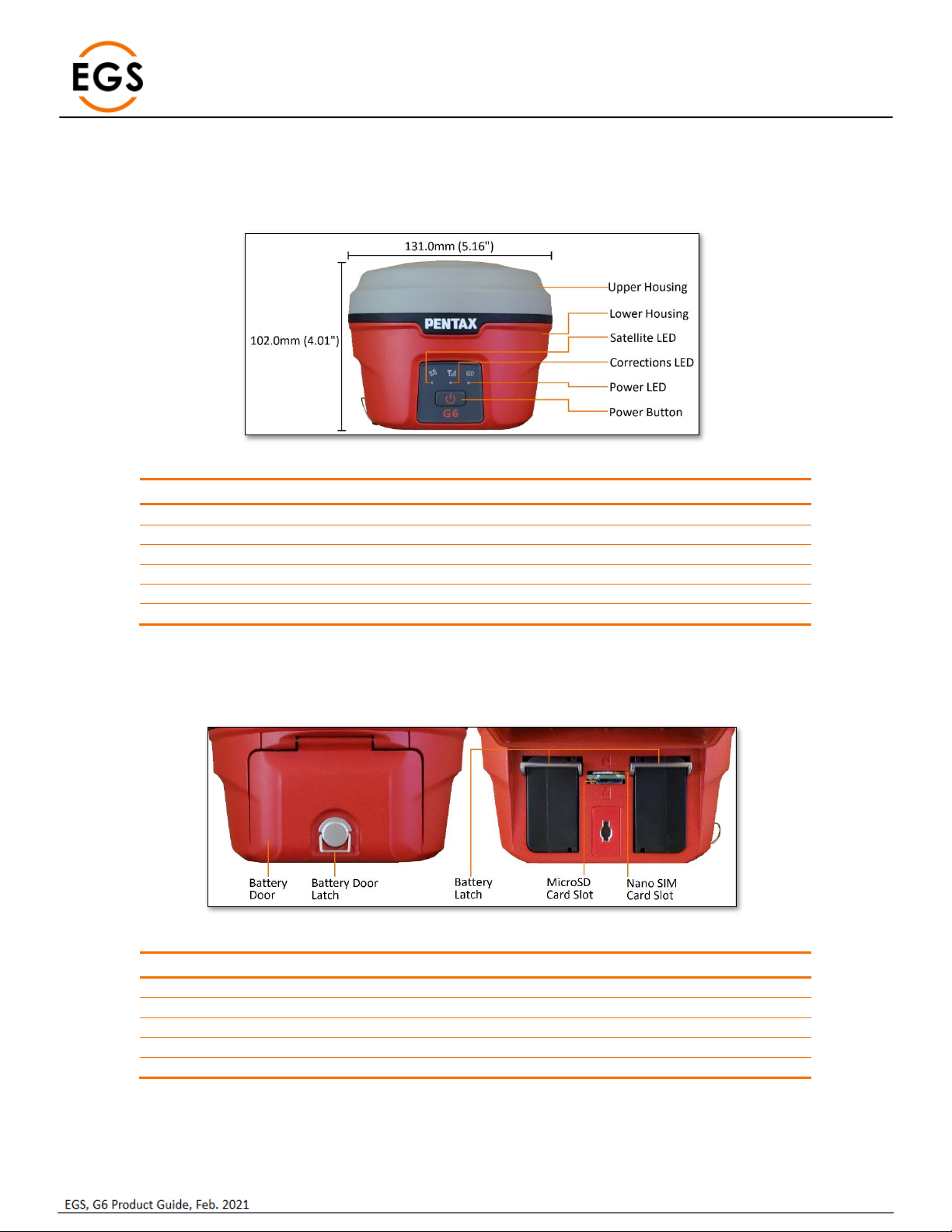
1.1 G6N Front Panel ..........................................................................................................................................................................3
1.2 G6N Battery Compartment..........................................................................................................................................................3
1.3 G6N Ports & Speaker...................................................................................................................................................................4
2G6 Basic Operation ............................................................................................................................................................................5
2.1 Power Button...............................................................................................................................................................................5
2.2 G6N Panel LEDs............................................................................................................................................................................5
2.3 Battery Compartment Door.........................................................................................................................................................6
2.4 Nano SIM Card.............................................................................................................................................................................6
2.5 Micro SD Card..............................................................................................................................................................................6
2.6 Installing a Battery.......................................................................................................................................................................7
2.7 Wired/Cable Connections............................................................................................................................................................7
2.8 G6N ARP ......................................................................................................................................................................................8
2.9 Antenna Height............................................................................................................................................................................8
2.10 Bluetooth ID.................................................................................................................................................................................9
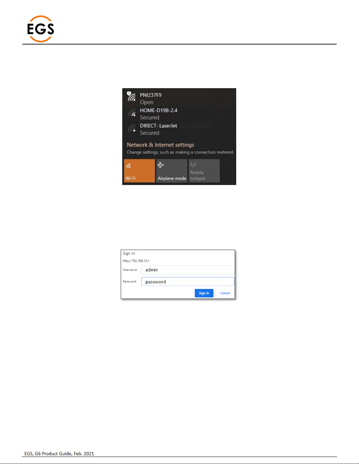
3Web UI .............................................................................................................................................................................................10
3.1 Status.........................................................................................................................................................................................11
3.2 Information................................................................................................................................................................................11
3.3 Satellites ....................................................................................................................................................................................12
3.4 Download ..................................................................................................................................................................................13
3.5 Management .............................................................................................................................................................................14
3.6 Settings......................................................................................................................................................................................15
3.6.1 Working Mode ...................................................................................................................................................................15
3.6.2 Device configuration ..........................................................................................................................................................18
3.6.3 NMEA Message..................................................................................................................................................................19
3.6.4 Relay Mode ........................................................................................................................................................................20
4G6 standard accessories ..................................................................................................................................................................22
4.1 Shipping Case.............................................................................................................................................................................22
4.2 Power.........................................................................................................................................................................................22
4.3 Battery Pack...............................................................................................................................................................................22
4.4 Battery Charger .........................................................................................................................................................................22
4.5 UHF antenna..............................................................................................................................................................................23
4.6 Accessories ................................................................................................................................................................................23
5Appendix 1 Default radio configuration...........................................................................................................................................24
6Appendix 2: Voice Messages............................................................................................................................................................25
7Appendix 3 G6N Specifications ........................................................................................................................................................26