EIGHT CHANNELS DYNAMIC CODE RECEIVER CH8HR (EN)
This microprocessor controlled eight channels receiver is designed to operate with large number of transmitters in wireless alarms and access
control systems using KEELOQ® dynamic signal coding offering highest level of security. The receiver features eight galvanic separated NO/NC relay outputs with
front panel LED channel indication and signal control output S. It operates with all Elmes Electronic made 433,92MHz band wireless detectors and transmitters
including RP501 and features warning signals of radio link failure, cabinet opening or tamper and low battery state in learned transmitters.
Each channel may have learned any number of transmitters with total number not exceeding 40. Learning next transmitter would delete first in memory. The need to
delete a lost transmitter requires deleting all in receiver’s memory and learning remaining transmitters again. The CH8H receiver offers range of applications including:
- wireless detector’s interface to any wired control panel monitoring alarm signals from Elmes Electronic wireless transmitters such as CTX, GBX, PTX and RP501
and UMB100H hand transmitter programmed to channel one arming and disarming the system;
- calling and wireless panic button with users having hand transmitters (e.g. AN200H or UMB100H) as personal panic button alarm triggers. In calling system, the
use of hand transmitter would set on a call lasting for earlier programmed time period. Two channel hand transmitters (e.g. DW200H or DWB100H) used as wireless
panic buttons may have one button used for quiet alarm function while the other used for a loud panic alarm.
OPERATION
Activating transmitter programmed to CH8HR receiver sets on respective channel relay output and illuminates the channel’s LED. Depending on programmed
operation mode (see programming procedures p.2) the receiver’s relay outputs are set on & off in one of two following modes:
1. Momentary (pulse) mode lasting from 0.5 second up to 4 hours.
2. Latching (on-off) mode setting relay output on and off by consecutive signals received from transmitter.
Output S generates two pulses on any channel relay set and one pulse on reset. Also, it signals low battery and radio link failure warnings according to settings made
with jumpers JP1, JP2 & JP3 (see table below). Multichannel transmitters and RP501 transmitter always set on/off adjacent relay outputs. Elmes Electronic PTX, GBX
and CTX wireless detectors signal alarms in two channels: motion detection in any of the eight channels and tamper alarm in channel eight - automatically assigned at
learning the detector to receiver procedure. The channel number eight signals also receiver’s power cut off, cabinet opening and wiring cut off.
Operating with RP501 transmitter in radio relay mode or with CTX3H and CTX4H detectors operating in open-close monitoring mode, the receiver’s outputs state
correspond to the transmitter’s inputs meaning that the outputs are set on for as long as the transmitter’s inputs are opened. In case of CTX4H, for as long as the
magnet stays away.
The receiver monitors battery state in Elmes Electronic transmitters type PTX50, GBX, CTX and RP. Detected low battery in one of the transmitters is signaled by
blinking of the front panel main LED and, if the JP2 is opened (see table), by output S shorted to receiver’s ground. The number of LED pulses in a series correspond
to channel number with low battery detected. The signaling sets off automatically after battery is replaced and transmission activated.
Identically, the CH8HR receiver signals failure of radio link in operation with transmitters PTX, GBX and CTX4H (CTX4H serial number > 610000). The transmitters
send identification signal every 10 hours. If any signal is not received by receiver within 24 hours time period (e.g. for reason of its failure) this will be warned by
blinking receiver’s main LED and, if JP2 is opened, output S shorted to ground. To activate this function, jumper JP3 should be set open.
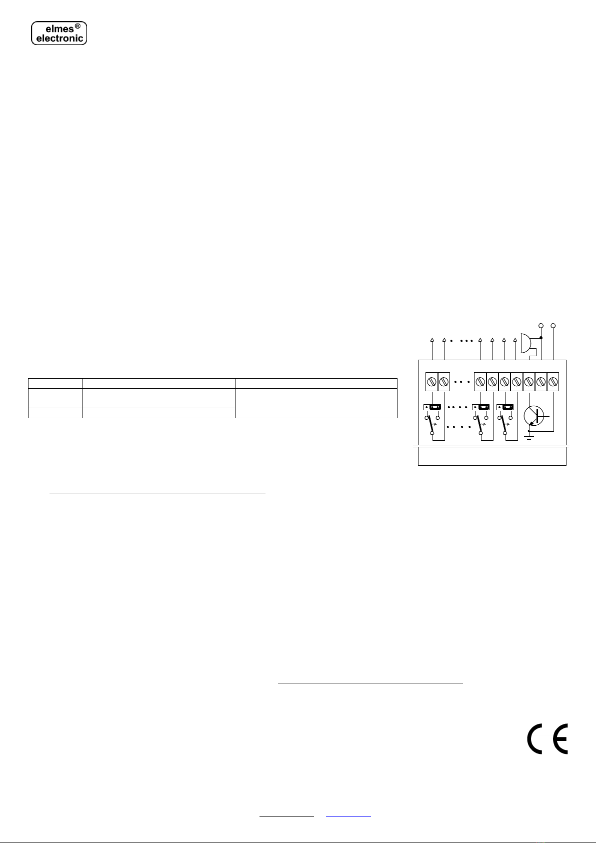
INSTALLATION & OUTPUTS SETTING CH8HR wiring diagram:
Receiver CH8HR is designed for indoor operation only within temperature range of 0 to +40
C. Operating range
with wireless detectors and transmitters highly depends on place of installation. High humidity, electromagnetic
power lines, nearby radio transmitters or metal screening may cause interference and reduce operation range.
Receiver’s wire antenna should be let loose downwards and not glued to wall. Jumpers placed next to output relays
on the receiver’s pc board are used for selecting standby mode NC (normally closed) or NO (normally opened).
Table - operating modes of output S
Two pulses on any output set on, one pulse
on output set off
Shorting to ground at low battery warning.
Radio link failure signaling if JP3 also opened
Pulses on channel 1 set on/off only
PROGRAMMING PROCEDURES
Programming is made with housing’s front panel taken off and the use of PRG switch on the receiver’s board.
1. Learning transmitter(s) to receiver's memory (maximum 40).
a) Press receiver's PRG switch for less than 2 seconds. The receiver’s central LED switches to red and the first
channel set on LED illuminates,
b) Shortly pressing the PRG switch select the required channel for programming transmitter to,
c) Press the PRG switch until the receiver’s LED switches to green,
d) Depending on type of programmed transmitter proceed as follows:
- for hand transmitters –double press the transmitter’s switch. For multi channel transmitters press switch number respectively to number of channels to program,
example: double pressing the 3rd switch in four ch. transmitter CH4H will program first three channels. The fourth channel will not be active in this receiver.
- for the PTX50 detector –set the detector internal transmission channel selector to 1 and activate two transmissions by moving hand in front of the detector,
- for the CTX3H, CTX4H wireless contacts –activate double transmission by double quickly moving magnet in and out of the CTX housing,
- for the RP501 transmitter (operation with radio link testing is not allowed) - set the required mode of operation and activate transmission by opening any of
its four inputs respectively to number of channels required, example: activating input 2 will program input 1 and 2, while 3 and 4 will not be programmed.
e) Slowly blinking LED in the receiver will indicate end of the procedure.
2. Setting the outputs’ set on time in selected channel.
a) Press receiver's PRG switch for more than 2 and less than 8 seconds. LED switches to red and next to green. The first channel LED illuminates.
b) Pressing the PRG switch select (illuminating LED indicates selected ch.) required channel for programming its output momentary set on time:
c) Press the PRG switch for longer than 2s, till the receiver’s LED switches to red.
d) Shortly press PRG switch and the LED switches to green (counting of set on time is started). When desired set on time has lapsed (up to 4 hours) press the PRG
switch again. The LED lights red and after next 2s blinking receiver’s LED indicates end of the procedure.
NOTE! To program latching (on/off) output mode of selected channel press the PRG switch three times at subcl. 2d with less than 2s intervals.
3. Deleting all transmitters from the receiver's memory.
Press receiver's PRG switch for more than 8 seconds (the receiver’s LED switches to red and next to green), until the receiver LED starts blinking and then release
the switch. Memory of the receiver is cleared but the channels' programmed modes of operation remain unchanged. To learn new transmitter(s) to the receiver's
memory follow procedure 1 above.
4. Deleting a single hand transmitter from receiver’s memory.
It is possible to delete a single hand transmitter from receiver’s memory under condition that the transmitter is in our possession. This tricky procedure requires
performing steps 1abc in learning procedure 1 above, while in step d first transmission must be sent from the transmitter to be deleted and second transmission from
any other transmitter or, by pressing other button in multi button hand transmitters. Receiver LED blinking red will indicate programming error –in this case
meaning that the transmitter is deleted. The receiver does not respond to signals send from deleted transmitter any more.
+
128 S
Receiver's board
_
12V
+_
Relay's outputs
NO
NC
NO
NC
NO
NC
+
Buzzer
Note: programming errors are indicated by fast blinking LED. The receiver sets off programming mode automatically if activity is not detected within 30 seconds.
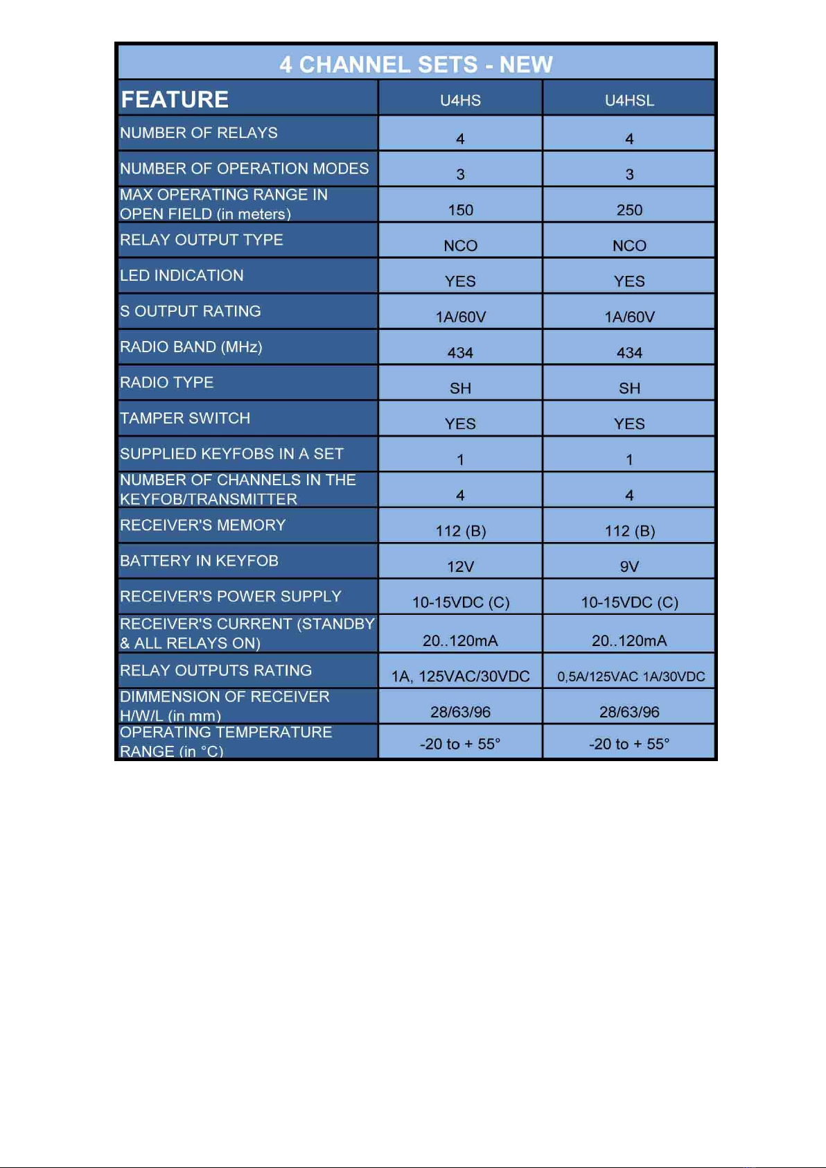
SPECIFICATION
-eight channels with NO/NC galvanic isolated relay outputs rating: 1A/24VDC or 0,5A/125VAC and LED indication;
-superhet 433,92MHz band receiver with front panel LED indication; output S for external siren and 40 transmitters memory;
-power supply 11 to 15VDC (nominal 12VDC) with 180mA max. current on all relay outputs set on.
Manufacturer’s limited warranty. Elmes Electronic products carry manufacturer’s one year limited warranty as from date of purchase. The warranty is limited to the
replacement of faulty original parts or repair defects of improper manufacture. Damage, faulty use or improper handling by the user or installer as well as any changes
in product’s hardware or software caused by the user or any other unauthorized person violets the warranty and all due repair costs will be charged. Elmes Electronic
shall not bear any liability for any personal or material damage resulting from its any product direct, indirect or partial failure to operate properly.
KEELOQ®is a registered trade mark of Microchip Technology Inc., USA.
ELMES ELECTRONIC, phone (+4871)7845961, fax 7845963, e-mail: elmes@elmes.pl www.elmes.pl
Elmes Electronic 07.2015. All rights reserved.