Static Transfer Switch
STS118
User Manual
Page 4 (24)
©2009. ELTEK VALERE DEUTSCHLAND GmbH. UM_STS118_E_R0.0
Table of Contents
1. Safety Instructions and Waste Disposal Rules ......................................................................6
2. General Information ......................................................................................................................7
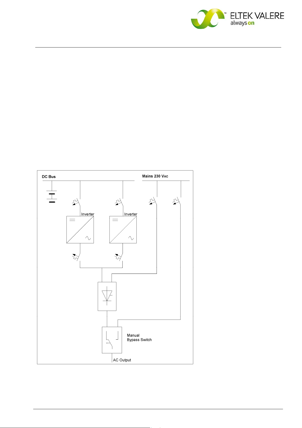
2.1 Example of use .........................................................................................................................................................7
2.2 Operating modes......................................................................................................................................................8
2.2.1 Inverter priority configuration.......................................................................................................................8
2.2.2 Mains priority configuration ..........................................................................................................................8
3. Type Range/ Main Data................................................................................................................8
3.1 Main output data......................................................................................................................................................8
3.2 Necessary equipment for STS118 assembly: ..................................................................................................9
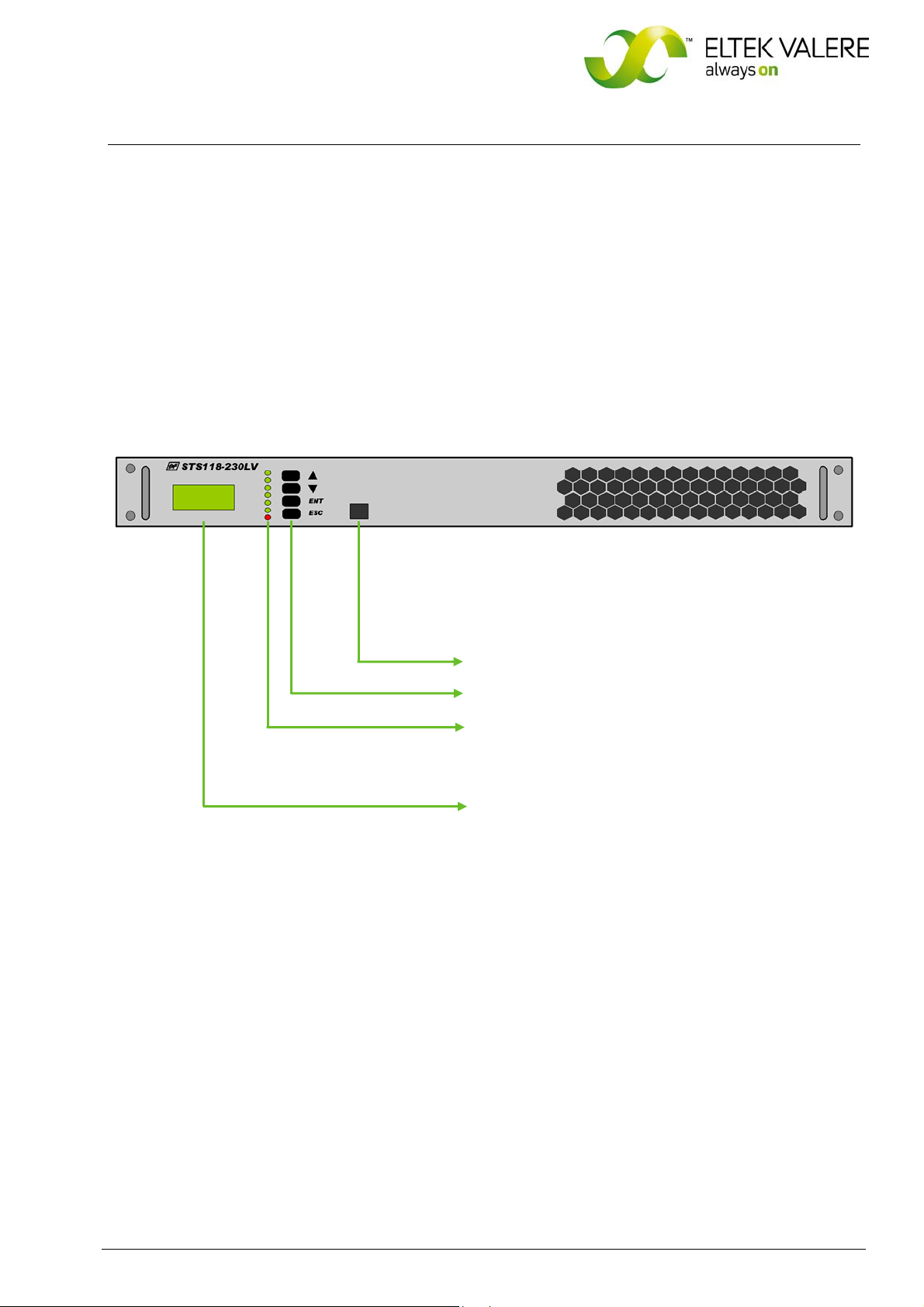
3.3 Front view: control elements, indicators ...........................................................................................................9
3.4 Electrical connections.......................................................................................................................................... 10
3.4.1 Pin assignment of the rear side backplane connectors...................................................................... 11
3.4.2 Pin assignment of the rear side CAN-Bus connectors X22 & X23 (RJ11):...................................... 12
3.4.3 Pin assignment of the front side Ethernet connector (RJ45):........................................................... 12
3.5 Cooling/Air flow direction ................................................................................................................................... 13
3.6 Communication interfaces ................................................................................................................................. 13
3.6.1 CAN-Bus........................................................................................................................................................... 13
3.6.2 Ethernet (Net Connection).......................................................................................................................... 14
4. Handling ........................................................................................................................................ 15
4.1 Storage .................................................................................................................................................................... 15
4.2 Commissioning....................................................................................................................................................... 15
4.3 Operation................................................................................................................................................................. 15
4.3.1 LED Indications............................................................................................................................................... 16
4.3.2 Adjustment keys........................................................................................................................................... 16
4.3.3 LC-Display: Indication of measured values and alarm messages ..................................................... 17
5. Parameter adjustment / Menu structure............................................................................. 18
5.1 Adjustable Parameters (Customer menu) ...................................................................................................... 18
5.2 Structure of the customer menu...................................................................................................................... 19
6. Maintenance ................................................................................................................................2
1
7. Trouble shooting......................................................................................................................... 21
8. Technical specifications ........................................................................................................... 23
8.1 Dimensional drawings .......................................................................................................................................... 24