6
MOUNTING THE MONITOR
The StudioVision Rackmount Monitor ts into any standard 19-inch
machine rack and takes two standard rack spaces (3U).
Use standard 10-32 or M6 rack screws to attach the monitor into
the rack at all four corners.
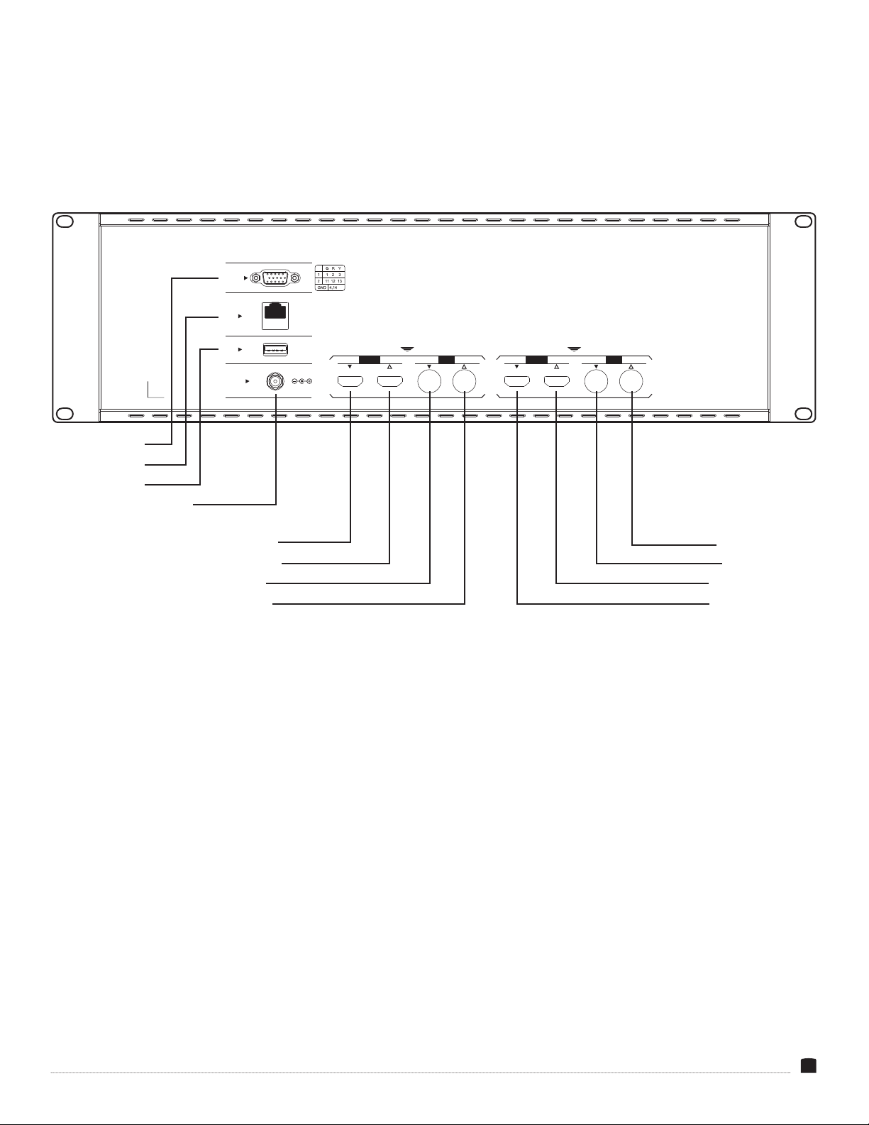
INPUT SIGNAL
The dual monitors can simultaneously display different video
signals or use loop-through outputs to display the same signal on
both monitors.
Connect the video source to an SDI or HDMI input. Once the
monitor is powered on, the picture is immediately visible. The
StudioVision monitor’s image processor automatically scales the
signal to t the screen.
Attach two separate sources to each monitor:
Plug HDMI sources into the HDMI inputs 1 and 2 on the rear panel.
Plug SDI sources into the SDI inputs 1 and 2 on the rear panel.
OUTPUT SIGNAL
The SDI and HDMI loop outputs on each monitor output the
unmodied video signals from their corresponding inputs to
downstream equipment.
Important: The SRM-7X2-4KH does not support cross conversion.
The HDMI OUT plug will not output an SDI signal.
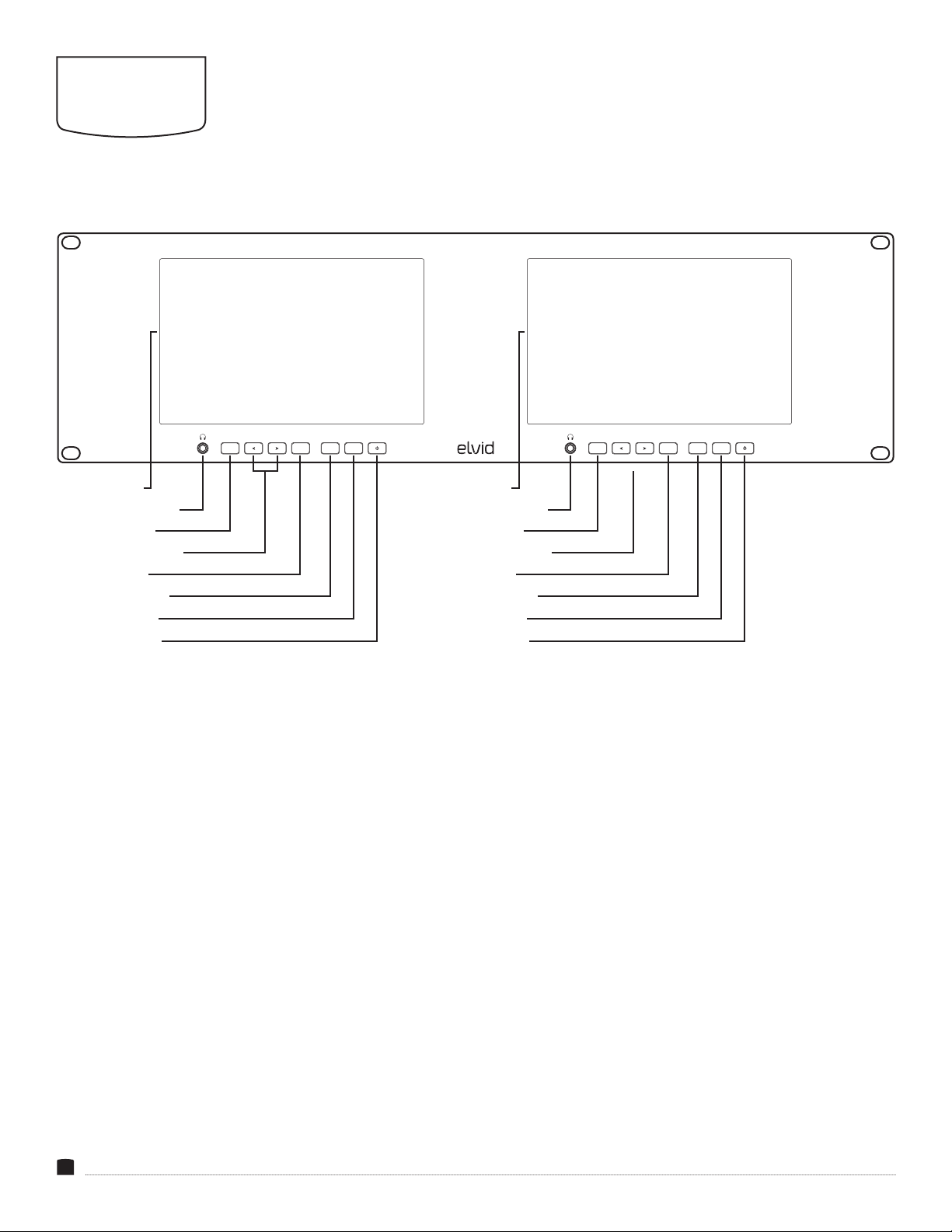
AUDIO
The StudioVision monitor accepts 8 channels of audio. The
headphone output for each side can be set to monitor a different
stereo pair of its incoming signal.
Note: The headphone jack outputs only the audio from its monitor’s
incoming signal. The audio signal does not loop unless the HDMI or
SDI signal is looped to the other monitor.
SETTING UP THE STUDIOVISION
RACKMOUNT MONITOR
USB PORT
User-dened LUTs can be imported via the USB port and stored in
the User1 through User6 options.
User-dened LUTs must be in .cube format, 3D size must be
17×17×17, and data and table order must be RGB. For the monitor to
recognize them, they must be named User1, User2, User3, User4,
User5, or User6 and placed in the root directory of the drive.
Connect a computer to the USB port on the rear panel to apply
rmware updates from Elvid when available. Firmware updates are
posted on the download page at www.elvidcinema.com.
CONNECTING TO A NETWORK
Connect the StudioVision dual monitor to a LAN via the ethernet
port on the rear panel.
The StudioVision monitor uses DHCP to obtain the IP address from
the network.
To manually assign an IP address to the StudioVision, see the
explanation of the System/DHCP menu below.
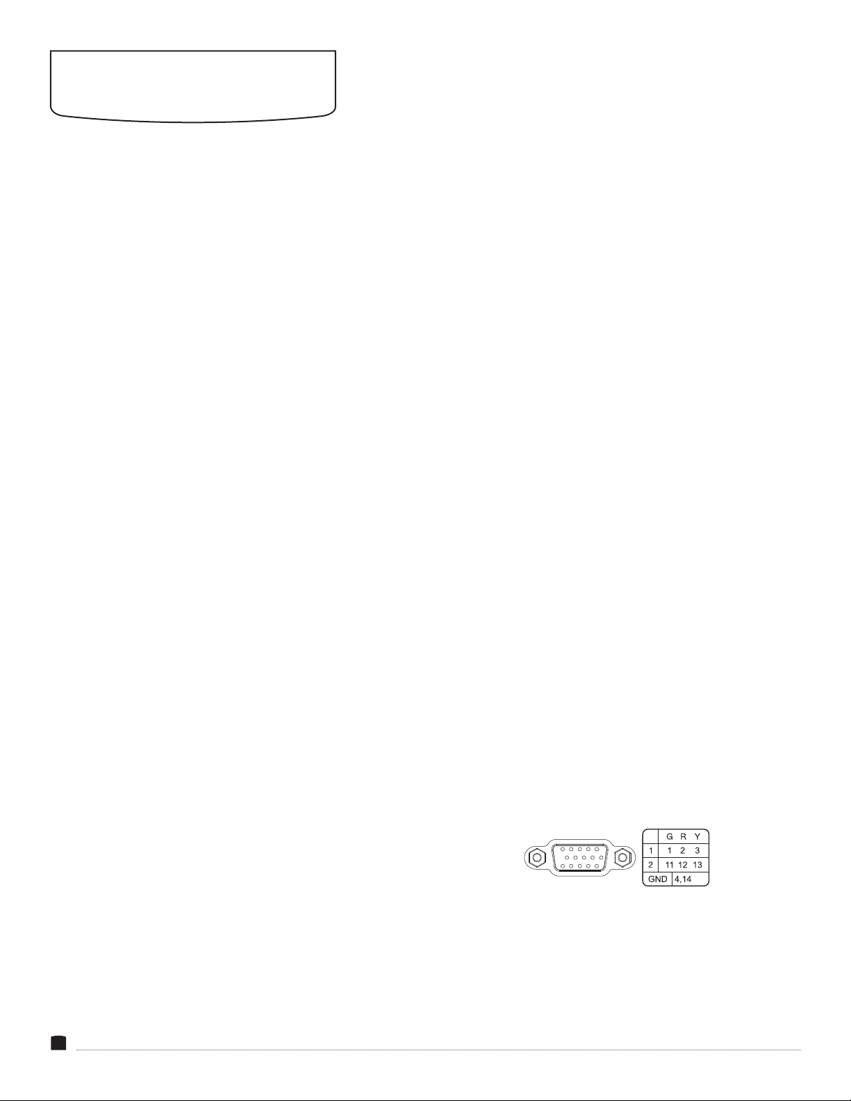
TALLY
The tally connector accepts signals from switchers and automation
systems, and you can use the StudioVision monitor to indicate the
signal’s status for on-air, preview, or broadcast applications. When
connected, the tally system will place a border around the active
signal�
Refer to the pin function diagram below, and your switcher or
automation system documentation to correctly wire the included
tally connector for compatibility.