CONTROLLER OPERATIONS, LCD SETTINGS
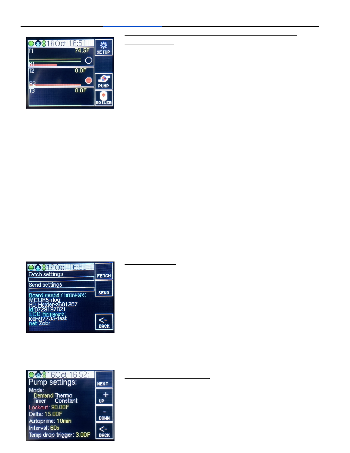
Home screen
Screen blinks every second, that's normal.
Large circle - Indicates the connection between the Mainboard and the LCD screen. Should be
green and may indicate an issue if it stays red.
Diamond - Indicates signal strength to a wifi connection, black/empty means no Wi-Fi connection,
and a full symbol (no black) indicates a strong Wi-Fi signal.
Snowman - indicates connection to server. 2 red dots indicate no connection and 2 green dots
indicate the controller is connected and reporting data to the server for display in the web portal.
Date/Time - Date and time
Menu icons
Setup - gives the id, firmware version, WiFi network name, mainboard model, ability to
send and fetch settings between controller and web portal
Pump - pump control settings such as, mode, lockout, Delta, autoprime, interval, tempdrop
trigger
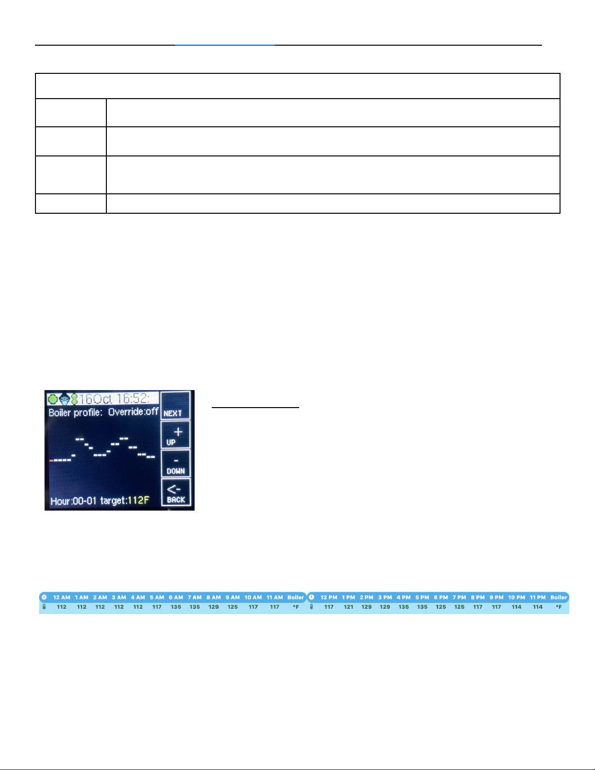
Boiler - settings for boiler profile and boiler control override
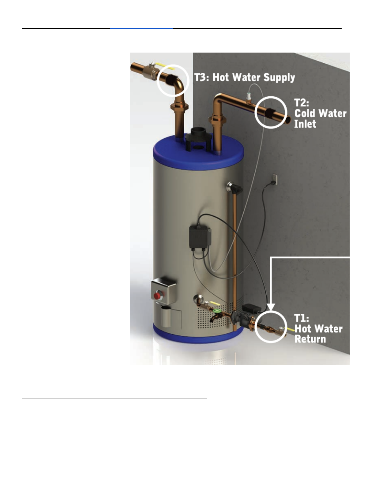
T1/R1 - The top right shows the current temperature of T1. The yellow line is a graph of the lockout
temperature setting. The green line represents T1 temperature as a line graph over time. The bottom
red line indicates whether R1 (relay 1, used for return pump actuation) has been running as a line
graph over time. The circle is black if the R1 pump is not currently running and red if the controller is
actuating R1 to turn on the pump meaning the pump is or should be running.
T2/R2 - The top right shows the current temperature of T2. The green line represents T2 temperature
as a line graph over time. The bottom red line indicates whether R2 (relay 2, used for boiler control)
has been running as a line graph over time. The circle is black if the R2 boiler control is at target
temperature and doesn't need to fire up the boiler. The circle is red if the temperature of T3 is below
the target temperature for this hour of the day (or if overwritten) and the boiler should fire up to get to
target temperature.
T3 - The top right shows the current temperature of T3. The green line represents T3 temperature as
a line graph over time.
Note: T1 is for R1/Pump Control. T2 is used for temperature drop pump activation (so its may
activate R1), and T3 controls whether the R2 boiler control wants the boiler to fire up or not.
Setup Screen
Fetch Settings - Hold down the button for fetch settings until the black bar beneath is completely
blue and it will take any settings saved in the web portal, and save them to this controller. This
function also happens every 20 minutes automatically. Only applies to controllers connected to the
web portal.
Send Settings - Hold down the button for send settings until the black bar beneath is completely
blue and it will take the settings currently on the controller and send and save them to the web portal.
If you do not do this while changing settings at the controller, the settings will revert the next time the
controller automatically fetches settings from the server, every 20 minutes. Only applies to controllers
connected to the web portal.
Board model / firmware - displays the mainboard model and firmware version.
ID - displays the ID for this controller.
LCD firmware - displays the firmware version of the LCD
Net - displays the Wi-Fi network name that the controller is trying to connect to. Only applies to
controllers connected to the web portal. Only applies to controllers connected to the web portal.
Pump Settings Screen
To navigate this screen, the work colored in red, indicates the setting that is selected for modification.
Pressing the up and down buttons moves the setting up or down, or left or right. Press the next
button to highlight in red the next setting wished to be changed. The settings only are submitted upon
hitting the back button. If web portal connected, make sure to send the settings to the server so they
do not get automatically overwritten because a web connected controller reads settings from the web
portal every 20 minutes, so you need the local settings sent, in order to sync them up so it doesn't
change.