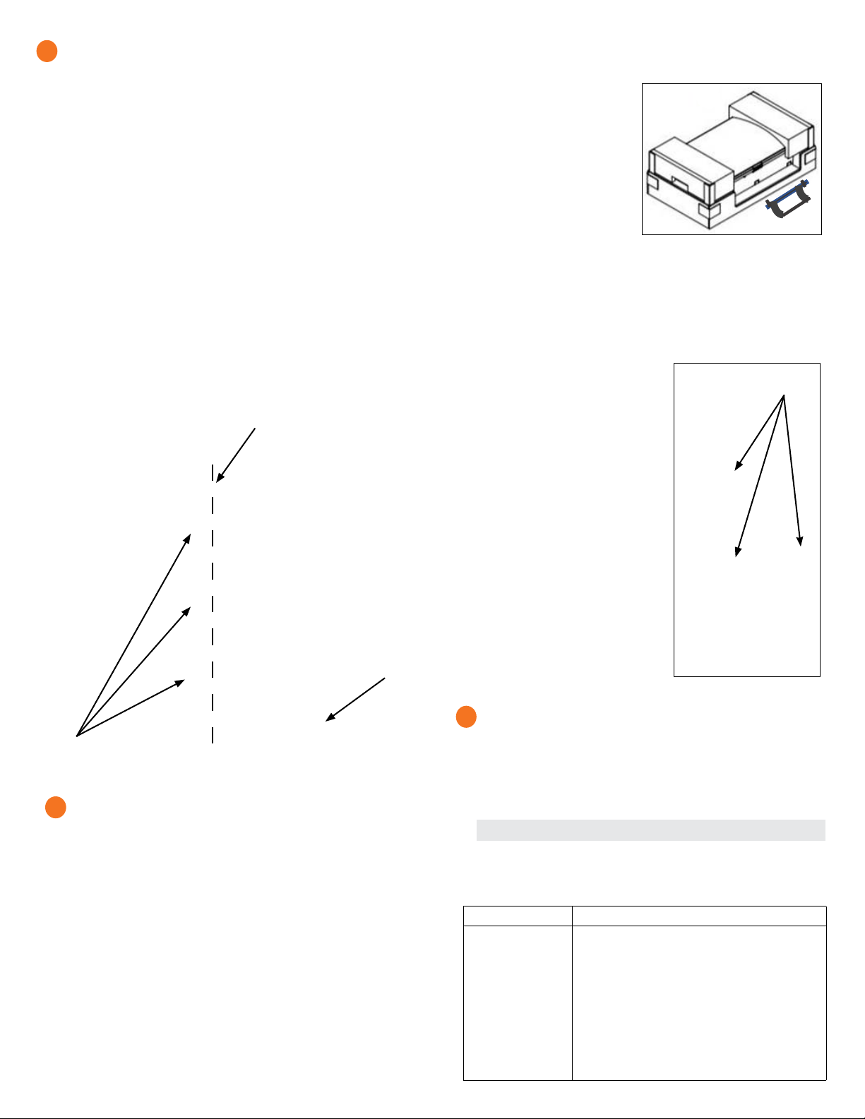
Install the wall-mount bracket
A ) Mark a plumb line over the wall stud as a guide.
* WARNING! Multiple risks. Make sure not to drill or attach into
electric wiring or pipes that are in the wall!
B ) Remove the wall mount bracket only from the shipping box.
C ) Place the wall-mount bracket on the wall so that the mounting holes in
the middle of the bracket align with the center of the stud. Use a level
to keep the bottom of the wall-mount bracket level.
D ) Use the #10, 1/4”, or 5/16” wood screws (or masonry attachments
if installing in masonry) to attach the bracket using one screw and
washer for each slot. The slot size of the Enpower wall mount bracket
is 8.5mm. Use an appropriately sized washer for each of the screws,
and check with a structural engineer and local standards for local
requirements.
E ) Verify that the wall-mount bracket is level, solidly attached to the wall,
and oriented for upright installation of the Enpower.
* WARNING! Risk of injury and equipment damage. Do not mount
an Enpower on a bracket that is not properly attached to a wall.
* WARNING! Risk of injury and equipment damage. Protect the
Enpower from impact damage and improper use.
2
3
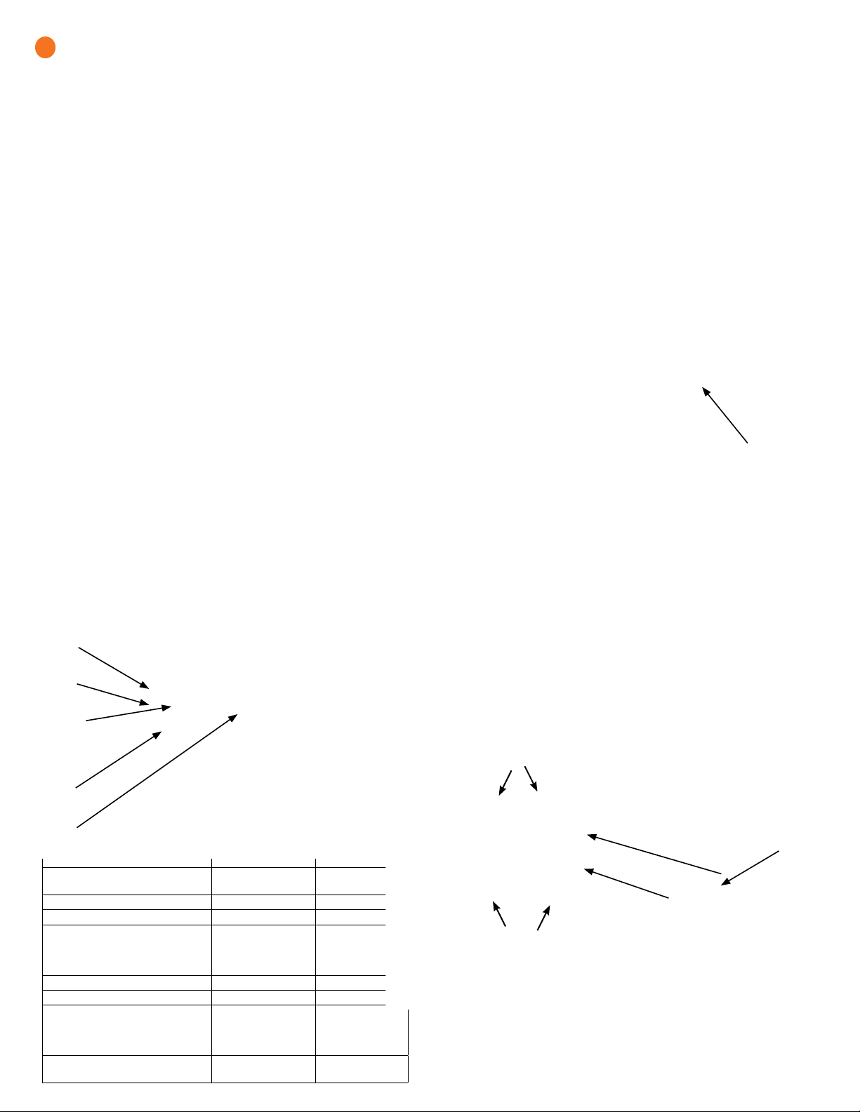
D ) Repeat on the other side with the second handle.
* WARNING! Risk of injury and equipment damage. Two persons
are required to lift the Enpower.
E ) Use the lifting handles, take the
Enpower from the packaging,
making sure it is top side up
(upright). Enpower is designed
only for vertical installation
without inclination (must be
level).
F ) Lift the Enpower slightly
above the installed wall mount
bracket and allow it to slide
down so that the bracket facing hooks set into both the top and
bottom shelves of the wall mount bracket.
G ) Allow the Enpower to slide down until the Enpower is fully seated on
the wall-mount bracket shelf.
* WARNING! Risk of injury and equipment damage. Do not release
the Enpower until you ensure that the Enpower is fully seated in the
wall-mount bracket shelf.
H ) For each handle, pull the plunger tabs
to release them and remove the lift
handles.
I ) Reserve the handles for the next
installation.
J ) On the bottom handle mounts, use the
two provided partial-threaded custom
M6 screws to secure each side of the
Enpower and tighten to 0.5 N•m (4.4
lb•in) or less.
The threaded portion of the screw
engages with the bracket, while the un-
threaded portion of the screw engages
with the hole in the bracket to prevent
vertical movement of the bracket.
* WARNING! Risk of injury and
equipment damage. Do not skip this
step. Without these screws in place, the
Enpower may fall and cause injury or
damage if bumped or shaken.
K ) Use the four ller plates, provided in the
lit kit, to cover the screws.
Enpower
Wall Mount Bracket Align with stud
Bracket
shelf
8.5 mm mounting
slots
Attach handles
Bracket facing hooks
on back of the Enpower
Unbox and mount the Enpower on the wall
* WARNING: Risk of injury. Take care when lifting. The Enpower is
heavy 38.5 kg (85 lbs).
* WARNING! Risk of injury and equipment damage. Avoid dropping
the Enpower. Doing so may create a hazard, cause serious injury, and/
or damage the equipment.
A ) Remove the upper Enpower box, and locate the slots on both sides of
the Enpower enclosure.
B ) Locate the lifting handles (sold separately) and check that the
plungers are extended and ready to engage into the Enpower slots.
C ) Align one handle on one side of the Enpower and press the handle
into the slots, and slide the handle toward the top of the Enpower
enclosure until it clicks into place. Check that the handle is secure.
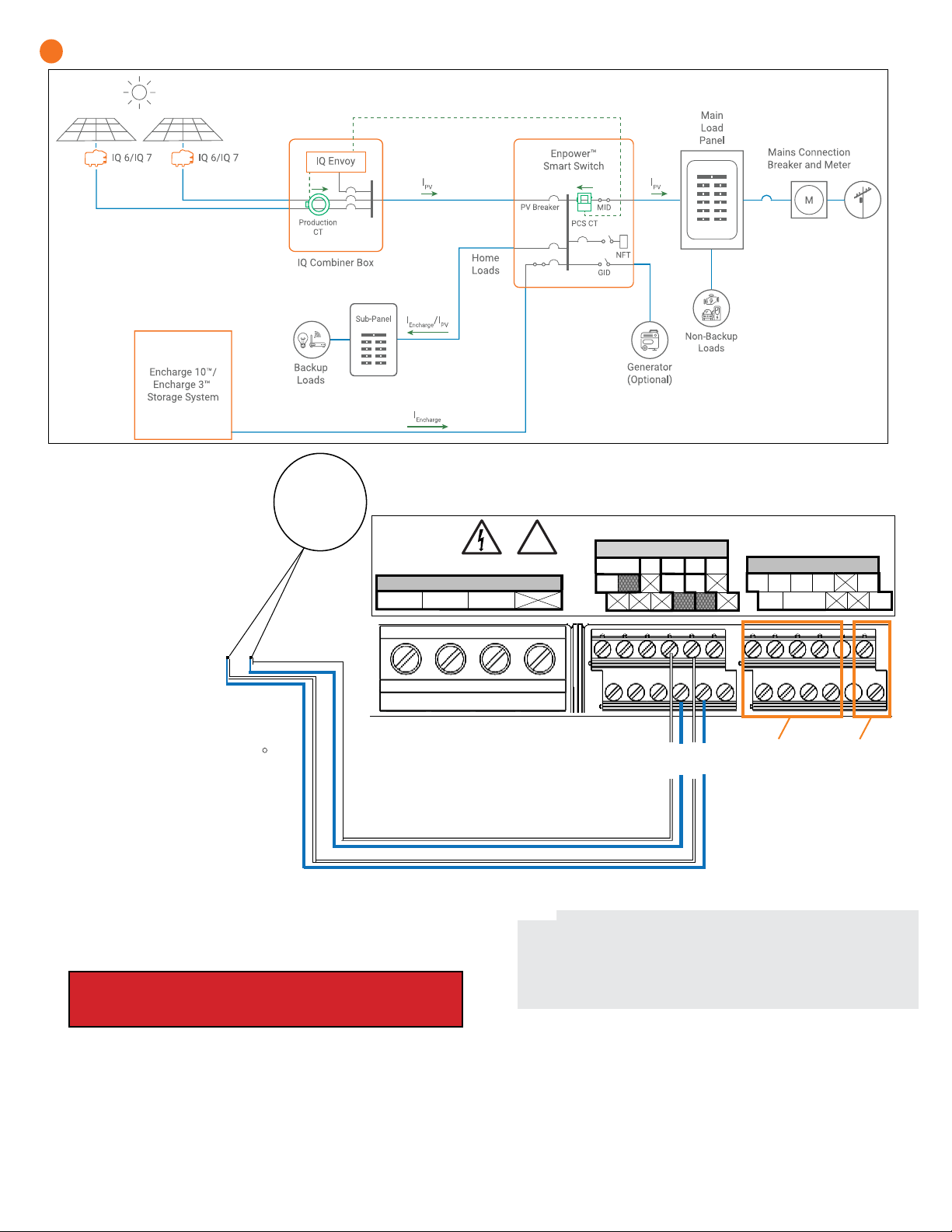
Install breakers as needed
The Enpower includes one two-pole 40A circuit breaker that feeds the
neutral forming transformer (NFT). You can install additional breakers,
if needed. You must follow all NEC and local electrical codes.
Install breakers as needed for the AC grid, main load, Enphase IQ Com-
biner, Enphase Encharge batteries, and generator. These breakers are not
included and must be ordered separately.
NOTE: You must install a backup loads breaker if required by local code.
* WARNING! Risk of injury and equipment damage. Use only the
breakers listed in this table.
List of allowed breakers and hold down kits:
Enphase Model No. Type and Eaton part no.
BRK-100A-2P-240V
BRK-125A-2P-240V
BRK-150A-2P-240V
BRK-175A-2P-240V
BRK-200A-2P-240V
BRK-20A-2P-240V-B
BRK-30A-2P-240V
BRK-40A-2P-240V
BRK-60A-2P-240V
EP200G-NA-HD-
200A
• Main Breaker, 2 pole, 100A, 25kAIC, CSR2100
• Main Breaker, 2 pole, 125A, 25kAIC, CSR2125N
• Main Breaker, 2 pole, 150A, 25kAIC, CSR2150N
• Main Breaker, 2 pole, 175A, 25kAIC, CSR2175N
• Main Breaker, 2 pole, 200A, 25kAIC, CSR2200N
• Circuit Breaker, 2 pole, 20A, 10kAIC, BR220B
• Circuit Breaker, 2 pole, 30A, 10kAIC, BR230B
• Circuit Breaker, 2 pole, 40A, 10kAIC, BR240B
• Circuit Breaker, 2 pole, 60A, 10kAIC, BR260
• Eaton type BR circuit breaker hold-down screw
kit, BRHDK125
Breaker installation positions are noted in the diagram.
4