ETS 5506-00 Manuale utente

CONTROLLED ENVIRONMENT
CHAMBER
Model 5506-00 & 5506-11
Plus
Packages D & E
Operating Manual
3/07
www.electrotechsystems.com

TABLE OF CONTENTS
Page
1.0GENERAL 1
1.1 Basic Chambers 1
1.2 Standard Packages 1
1.2.1 Chamber Specifications: 2
1.2.2Pkg.D: 2
1.2.3Pkg.E 3
1.3 Unpacking 3
2.0CHAMBER 5
2.1 Description 5
2.2Installation 6
3.0 PACKAGE SYSTEMS 6
3.1 Package D 6
3.1.1 Description 7
3.1.2 System Function 8
3.1.3 Installation 8
3.1.4 Operation 10
3.1.5Calibration 10
3.1.6 Troubleshooting 11
3.1.6 Specifications 11
3.2 Package E 12
3.2.1 Description 12
3.2.2 System Function 16
3.2.3 Installation 17
3.2.4 Operation 19
3.2.5Calibration 20
3.2.6 Troubleshooting 21
3.2.7 Specifications 23
3.2.8 Model 5465 Dry Gas Dehumidification System (Optional) 24
3.3 Replacement Parts 25
4.0WARRANTY 26

1
1.0 GENERAL
Many applications, such as electronics, medical, pharmaceutical and research
require a controlled environment for testing, assembly or storage. The Model 5506 is
designed to meet these requirements. The Model 5506 is available in standard or
custom configurations to meet specific customer requirements.
1.1 Basic Chambers
Model 5506-00: Enclosure only without glove ports
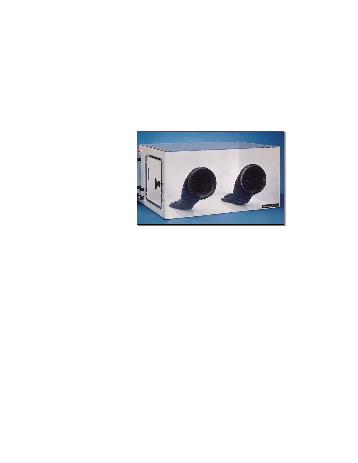
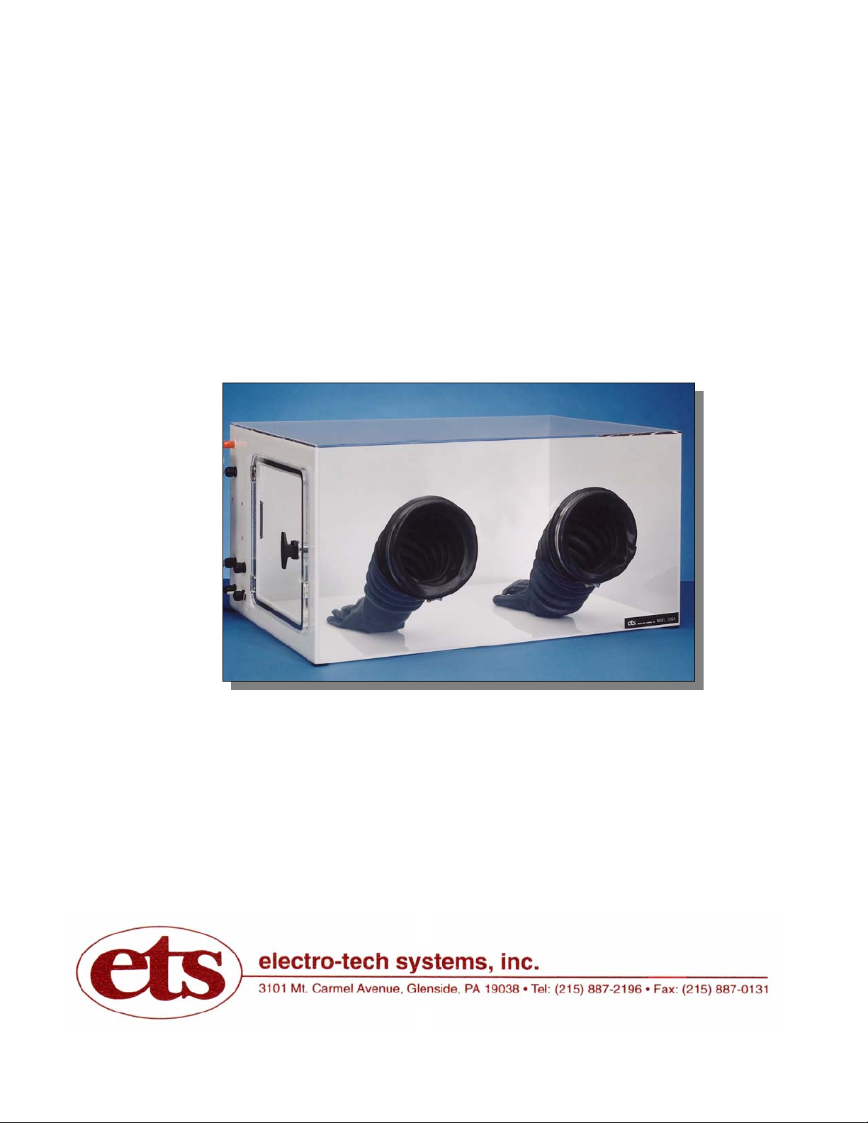
Model 5506-11: Enclosure only with 8” (203mm) glove ports (Fig. 1.1-1)
Figure 1.1-1: Model 5506-11
1.2 Standard Packages
The ability of the chamber to reach and then hold a given humidity level along
with humidity gradients is a function of the chamber (size, configuration etc.),
temperature, operating systems and controllers used. The following packages
provide solutions to most dehumidification applications. Chambers can also
be custom configured to meet special user requirements.
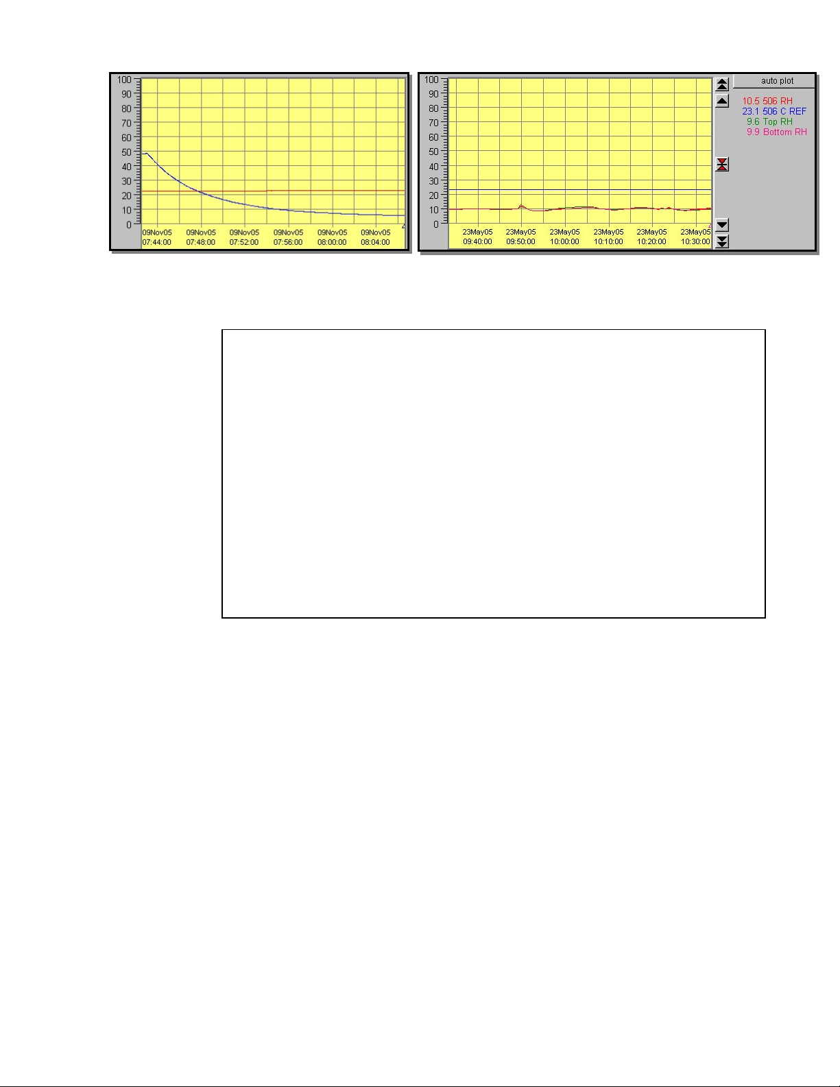
The following charts show the time typically required to decrease and
increase humidity (Blue = RH, Red = T °C) plus humidity gradients using
an ETS Controller in conjunction with the Model 5461 Desiccant/Pump
Dehumidification System.

2
Rate of humidity decrease Low humidity gradient
1.2.1 Chamber Specifications
1.2.2 Package D:
This configuration incorporates a single point controlled valve
(factory set to 5% RH; other values available) to regulate the flow of
nitrogen, dry air or other dry gas to provide controlled
dehumidification in the chamber at a single point. This system,
utilizing the ETS Model 5311 Controlled Gas Dehumidification
System, shown in Figure 1.2-1, is primarily used for storage or
single use applications.
Material: Fan: 32 cfm (900 l/min)
¼” (6mm) clear acrylic front, top (Specify 115 or 230VAC)
¼” (6mm) white, rear, side, bottom Access Ports (left side):
3/8” (9mm) white left side 2x¼” (6mm) hose barbs
1x1” (25.4mm) Hose barb
Construction: 1x½” (12mm) compression fitting
6-panel, PS30 welded seams 1x1½” (31.4mm) cable pass through
Door (left side): Dimensions: 24”Wx18”Dx15”H
½” (12mm) clear acrylic with ½-turn latch (61x46x38cm)
Seal: ¼” (6mm) Poron, non-setting gasket Weight: 41 lbs (19kg)
Gloves (when configured):
.018” (0.5mm), replaceable hands
natural rubber, accordion sleeves,
8” (203mm) ports
Operating Range:
Humidity: <1 – 100%
Temperature: <32 – 135 °F (0-55 °C)

3
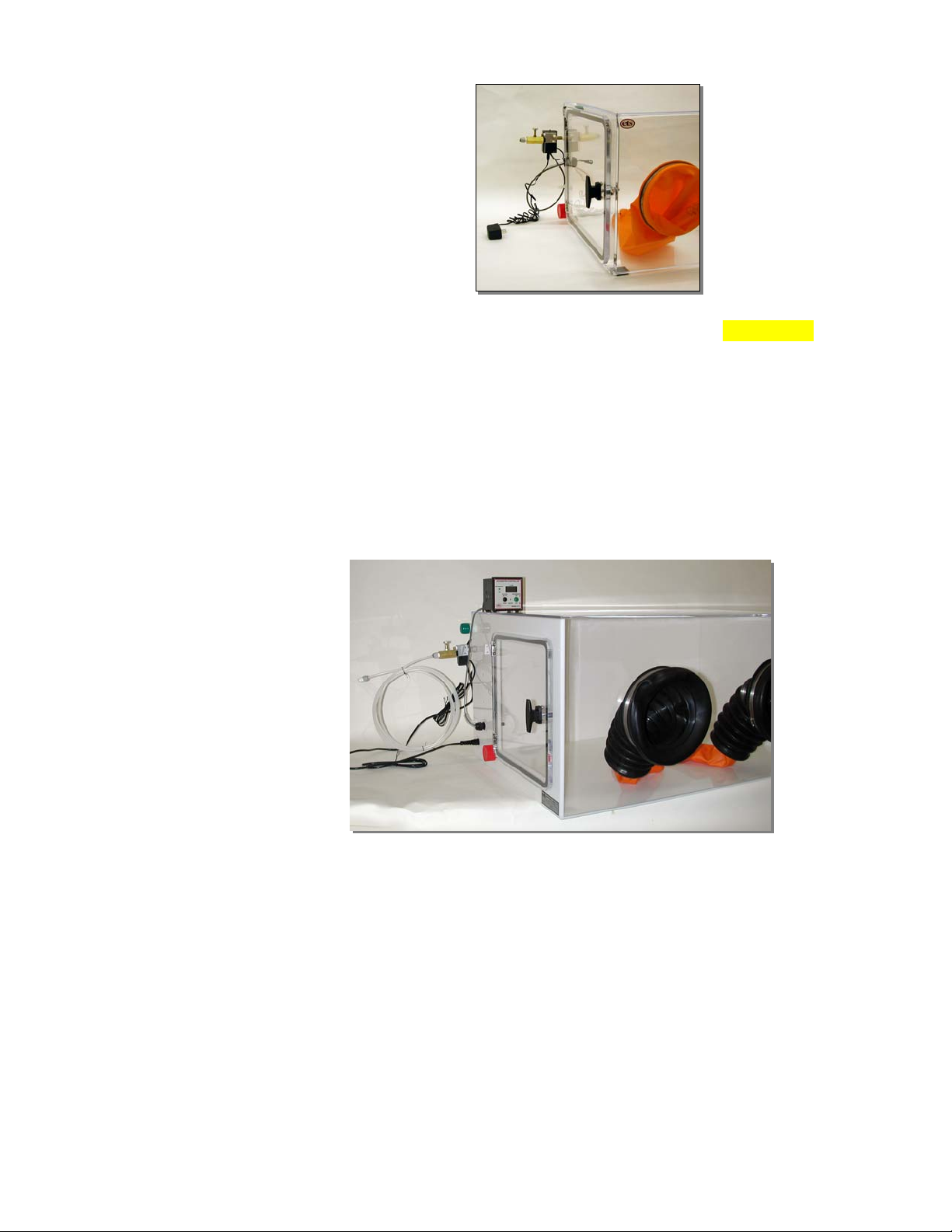
Figure 1.2-1: Package D Controlled Valve System 5506 None
1.2.3 Package E:
This configuration incorporates an adjustable dehumidification
control system, shown in Figure 1.2-2, utilizing the ETS Model 5112
Dehumidifier Controller and the Model 5461 Desiccant/Pump
Dehumidification System. The controller can measure and display
humidity over the entire range, but controls humidity only from 0 to
55% RH. Optionally, the Model 5465 Dry Gas Dehumidification
System can be used. (Ordered separately, not part of Pkg. E.)
Figure 1.2-2: Package E Dehumidification System
1.3 Unpacking
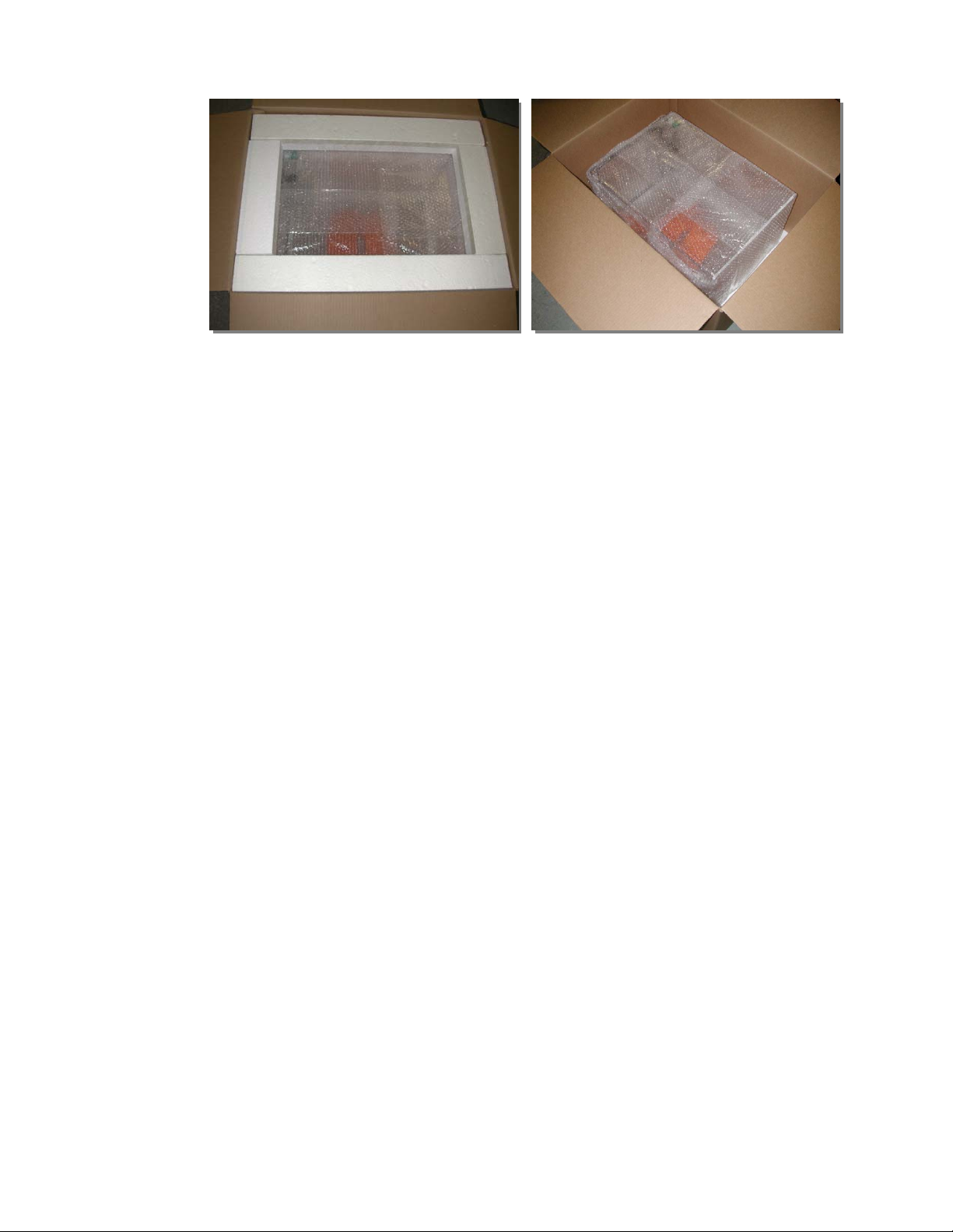
Figure 1.3-3 shows the chamber in its shipping carton. Unpack the
chamber and accessories from the shipping cartons and inspect for any
damage. When handling the chamber DO NOT use any of the fittings or
the door handle as a grip or for leverage. Lift the chamber by placing your
hand all the way into the glove port and grabbing hold of the chamber wall
or gripping around the outside of the chamber. If an item is missing or
broken please contact ETS immediately at 215-887-2196 x226 and
photograph the damage to both chamber and shipping carton. Save all
boxes and shipping material until the system is operational!

4
Figure 1.3-3: Chamber in shipping carton
Chambers only and with standard Package D or E configurations
operating instructions are contained in this Operating Manual. Each
chamber system includes the following:
Model 5506-00
1. Chamber without glove ports with 12”x12” (30x30cm) door
with gasket seal and inlet/outlet ports for accessories.
2. Pliable sealer
3. Operating Manual
Model 5506-11
1. Chamber with glove ports, 8” (203mm) gloves, 12”x12”
(30x30cm) door with gasket seal, inlet/outlet ports for
accessories.
2. Pliable sealer
3. Operating Manual
Model 5506-00, Package D
1. Chamber
2. Model 5311 Controlled Valve assembly
3. Pliable sealer
4. Operating Manual
Model 5506-00, Package E
1. Chamber
2. Model 5461 Desiccant/Pump Dehumidification System.
Includes pump (110 or 220 VAC), desiccator and 12’ (3.7m)
of clear plastic tubing.
3. Model 5112 Automatic Humidity Controller. Includes
humidity sensor, IEC power cord (North American plug).
4. Operating Manual

5
2.0 CHAMBER
2.1 Description
The Model 5506 is a 9.0 cubic foot (0.26 cu. m), sealed chamber
fabricated from 0.25” (6mm) and 0.375” (9.5mm) clear and white acrylic
and measures 36”Wx24”Dx18”H (92x61x46 cm). Access to the chamber is
through a 12” (30.5cm) square opening. A heavy-duty, 0.5” (13mm) clear
acrylic door, secured by a single ½-turn latch, along with a compression
resistant gasket ensures an airtight seal when the door is locked. A 1.25”
(32mm) diameter pass-through is provided for passing cables and/or
tubing through the chamber wall. A pliable reusable sealer seals the
opening. The access door and all fittings are located on the left-hand side
of the chamber as shown in Figure 2.0-1. Additional holes may be
positioned elsewhere as an option.
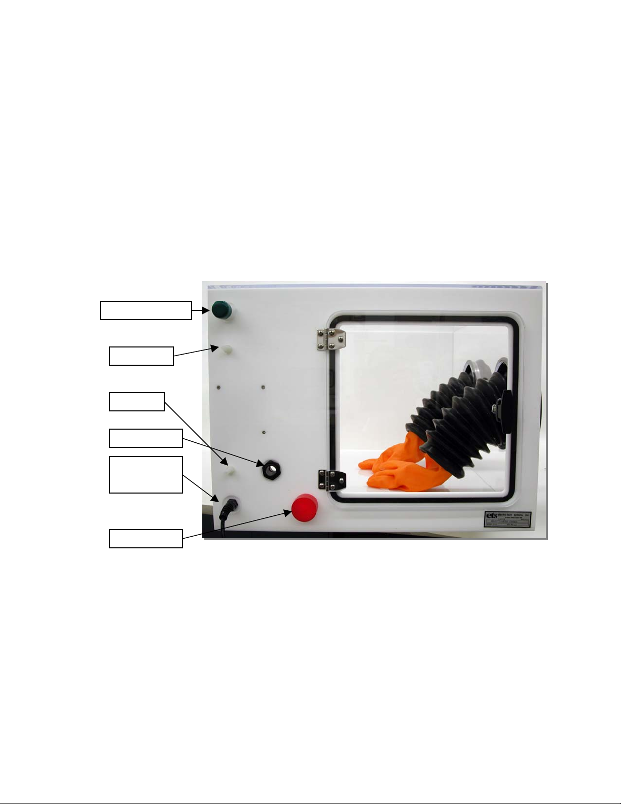
Figure 2.0-1: Chamber access door and fittings
The humidity level within the chamber is reduced using either dry gas
(usually dry nitrogen or dry air) injected into the chamber or a
desiccant/pump drying system. The desiccator contains a self-indicating,
renewable drying agent (Anhydrous CaSO4) and is mounted externally to
the chamber. A small pump draws air from the chamber and forces it
through the desiccator back into the chamber. This circulating system is
capable of producing humidity levels below 10% RH within the chamber
(Actual lower humidity limit may be determined by the object placed in the
chamber).
Humidifier In
p
u
t
Dr
y
Air In
Sensor Fittin
g
Air Ou
t
Fan Power
Cord
Access Hole

6
2.2 Installation
Place the chamber on an appropriate support surface such as a bench or
desk. Open the latch by turning the handle counterclockwise until the cam
turns away from the chamber wall and then open the access door. Place
the object(s)to be stored or tested inside the chamber and feed any cables
through the cable pass-through located at the rear of the left panel. Seal
the opening using the supplied pliable sealer.
3.0 PACKAGE SYSTEMS
Model 5506 Chambers configured as Package D or Package E feature automatic
dehumidification control.
The Model 5311 and 5112 Dehumidification Controllers used in these packages
operate in a similar manner. When the measured humidity exceeds the set point
by more than 0.5% RH (Model 5112), a solid-state control circuit turns on a
solenoid valve or pump. When the valve is activated, dry gas is injected into the
chamber, or the pump is turned on to circulate chamber air through the
desiccator, absorbing moisture and lowering the humidity level and then back
into the chamber. When the humidity level set point is reached, the controller
turns off the valve or pump. The valve or pump then cycles on and off
automatically as required by the controller to maintain the humidity level at the
desired set point.
3.1 Package D
Many applications require the accurate control of relative humidity at a
specific point below ambient for long-term storage or test applications.
Package D incorporates the Model 5311 Controlled Dry Gas System to
meet these requirements. The controlled solenoid activated valve
regulates the amount of dry gas required to both maintain a dry
environment and conserve the amount of dry gas used in the Model 5506
Chamber.
The Model 5311 is self-contained and comes complete with a controlled
solenoid valve, adjustable flow control valve, universal input voltage 12
VDC power module (90-260 VAC, 50/60 Hz), 5% RH sensor with ½” NPT
compression fitting plus a ¼” NPT quick disconnect fitting for ¼” polyflo
tubing.
The standard sensor supplied with the Dry Gas System has a fixed set
point of 5%. Sensors with other humidity set points are available as an
option. Supplied sensors cannot be reprogrammed to other set points. The
Model 5311 is capable of maintaining the humidity level to better than ±3%
of the fixed controller set point with a measurement accuracy of ±2% R.H.

7
3.1.1 Description
The Model 5311 Controlled Dry Gas System consists of two (2)
basic components: a humidity sensor and a controlled solenoid
valve with adjustable flow regulator.
The standard humidity sensor is an integrated unit measuring
approximately 1”Lx.44”Wx.375”D (25x12x10mm) that plugs into a
24” (61cm) multi-conductor cable that is hard-wired to the control
module. Longer cable lengths are available as an option. A
temperature compensated capacitive sensing element where
capacitance is proportional to humidity is used to detect the relative
humidity level. This sensor is programmed at the factory to produce
a digital output around a pre-selected set point. The standard
factory setting is 5% RH. Other fixed RH set points are available as
an option. Contact ETS to order.
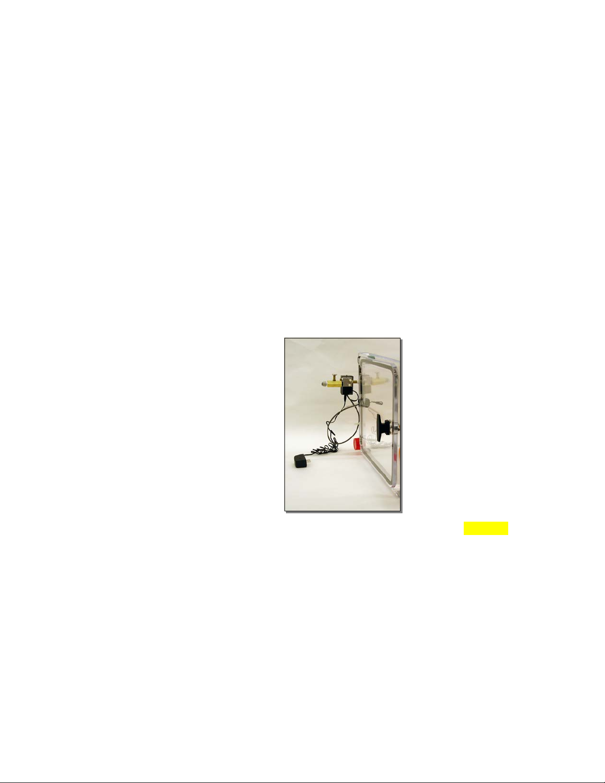
The sensor is mounted to the wall of the chamber using the ½” NPT
compression fitting, shown in Figure 3.1-1. Other mounting
configurations can also be used to meet the user’s specific
requirement.
Figure 3.1-1: Sensor mounted in compression fitting No 5506 Ph
The 36” (91cm) hard wired cable provides the input/output
interconnect between the Control unit and the Humidity Sensor.
The sensor end is fitted with a flat, 4-pin female receptacle with the
following pin-out configuration:
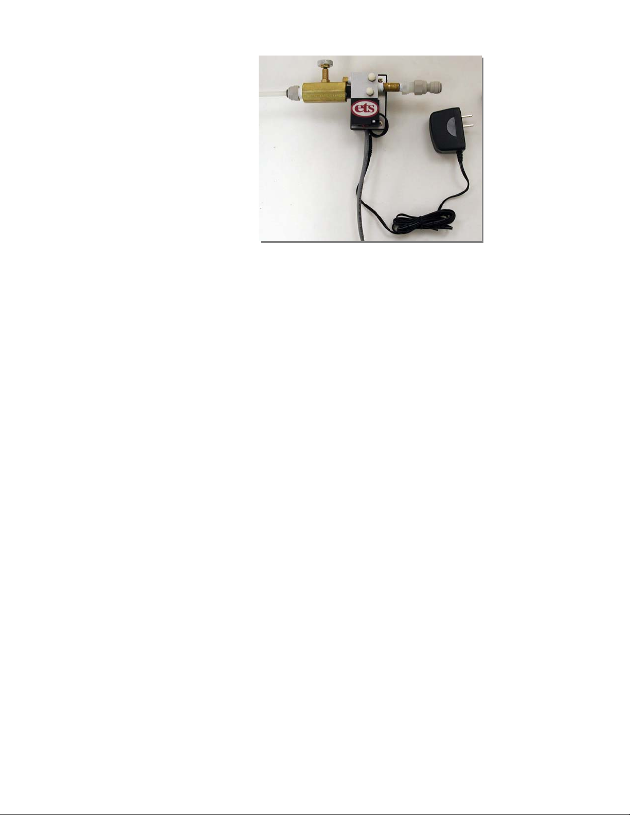
The Control/Solenoid/Flow Regulator unit is shown in Figure 3.1-2.
It will be referred to as just the Control Unit.

8
Figure 3.1-2: Control/Solenoid/Flow Regulator unit
The Control Unit is designed as a complete assembly. There are no
user controls except the flow regulator adjust knob. The only
indicator is a Green LED that indicates the solenoid is on and
supplying gas to the chamber.
3.1.2 System Function
The Humidity Sensor measures the relative humidity inside the
chamber. If the humidity measured in the chamber exceeds 7% RH
the solenoid valve is powered and dry gas is injected. When the
humidity inside the chamber drops to 4% RH the solenoid valve is
deactivated, shutting off the flow of dry gas. The valve will then
cycle on and off automatically as required by the Controller to
maintain the specified humidity level.
A 12V DC universal power module is used to power the Model
5311. It operates from 90-260 VAC, 50/60 Hz. For international
applications the user will have to provide the appropriate adapter
plug to convert the standard North American 2-prong plug to mate
with the available power (MAINS) outlet.
3.1.3 Installation
3.1.3.1 Initial Check Out
Inspect the Control unit and Sensor and inspect for any
visible damage. If no damage is observed then check out the
system as follows:
1. The Humidity Sensor is pre-wired to the control unit when
shipped.
2. Plug the low voltage connector from the power module
into the power jack located on the bottom of the Control
Questo manuale è adatto per i seguenti modelli
1
Indice
Altri manuali ETS Camera climatica