
EVOC EC4-1812CLDNA Manuale utente

EC41812CLDNA
EPIC Single Board Computer with
CPU/Memory/VGA/LVDS/USB/COM
/SATA/LAN/Audio
Version: A1

Announcement
What containedin this User Manualdoes not represent the commitments of EVOC
Company. EVOC Company reserves the right to revise this User Manual, without
priornotice,andwillnotbeheldliableforanydirect,indirect,intendedorunintended
lossesand/orhiddendangersduetoinstallationorimproperoperation.
Before purchasing, pleasehave a detailedunderstanding of the product performance
toseewhetheritmeetsyourrequirements.
EVOC is a registered trademark of EVOC Intelligent Technology Co., Ltd. All
trademarks, registered trademarks, and trade names used in this User Guide are the
propertyoftheirrespectiveowners.
EVOCIntelligentTechnology Co.,Ltd.©2009,CopyrightReserved.Nopartofthis
manual can be reproduced in any form or by any means, such as in electronic or
mechanicalway,withoutpermissioninwritingfromEVOC.
SafetyInstructions
1. Beforehandlingyourproduct,readtheuser’smanualcarefully;
2. Any board or card not ready to be installed shall be kept in the antistatic
packaging;
3. Before taking board or card from antistatic packaging, put your hand on
groundedmetalobjectforawhile(about10seconds)toeliminatestaticonyour
body;
4. While holding a board or card, please do wear static protective gloves; always
holdaboardbyitsedges;
5. Before inserting, removing or reconfiguring motherboard or expansion card,
firstdisconnectthecomputerandperipheralsfromtheirpowersources;
6. Before removing boards or computer, turn off all power resources firstly and
disconnectthepowercordfrompowersource;
7. For PC Box products, when inserting or removing boards, disconnect the
computerand peripheralsfromthepowersourcesfirstly;
8. Beforeconnectingorunplugginganyequipment,makesureallpowercordsare
unpluggedinadvance;
9. Toavoidunnecessarydamagecausedbyturningon/offcomputerfrequently,wait
atleast30secondsbeforereturningonthecomputer.

Contents
Chapter1ProductIntroduction ................................................................................1
Overview ............................................................................................................1
EnvironmentandMechanicalDimension .............................................................2
PowerConsumption ............................................................................................2
Microprocessor ...................................................................................................2
Chipsets..............................................................................................................2
SystemMemory..................................................................................................2
VideoFunction....................................................................................................2
NetworkFunction................................................................................................2
AudioFunction ...................................................................................................3
CFCard ..............................................................................................................3
SATA Function....................................................................................................3
PowerFeature .....................................................................................................3
ExpansionBus ....................................................................................................3
I/OFunctions ......................................................................................................3
Watchdog Function..............................................................................................3
Chapter2Installation...............................................................................................4
ProductOutline ...................................................................................................4
LocationsofInterfaces ........................................................................................5
JumperSettings...................................................................................................6
InterfaceforPower,HardDisk,WirelessNetworkCardIndicators........................7
LVDSBacklightControl......................................................................................7

USBInterface..................................................................................................... 8
SerialPort........................................................................................................... 8
VideoInterface ................................................................................................... 9
NetworkInterface ............................................................................................. 11
PowerInterface................................................................................................. 11
AudioInterface................................................................................................. 12
MultifunctionInterface ..................................................................................... 12
DigitalI/OInterface.......................................................................................... 13
SATA Interface ................................................................................................. 13
CFCard............................................................................................................ 14
MiniPCIEInterface.......................................................................................... 15
Chapter3BIOSSetup ........................................................................................... 16
Advanced ......................................................................................................... 17
Chipset............................................................................................................. 22
PCIPnP............................................................................................................. 23
Appendix.............................................................................................................. 24
Watchdog ProgrammingGuide.......................................................................... 24
DigitalIOProgrammingGuide ......................................................................... 26
I/O AddressMap............................................................................................... 29
IRQAssignmentTable ...................................................................................... 31

Chapter1ProductIntroduction
EC41812CLDNA 1
Chapter1ProductIntroduction
Overview
This board is a sort of embedded motherboard compliant with EPIC single board
specification, which is developed basing on the Intel® Atom platform; the board
adopts pin interfaces and is abundant in integration functions, complete in
performanceandhighinreliability;itsmainfeaturesareasfollows:
◆ Support ATOMN270CPU;
◆ Intel®945GSE+Intel®ICH7Mchipset;
◆ Onboard512MBDDR2 memory(couldbeexpandedto 1GB);
◆ Support VGA and LVDSdualdisplayfunction;
◆ Providesix USB2.0 highspeedinterfaces;
◆ Provideone 10/100/1000Mbps Ethernetcontroller;
◆ ProvideoneHDA audiointerface;
◆ Provide two SATA harddiskinterfacesandoneCF cardinterface;
◆ Provide eight COMs, four of which support RS232 and the other four
supportthreeline TTL level;
◆ Provideone MiniPCIEinterface;
◆ Provideone4bitinputand4bitoutputdigitalI/Ointerface;
◆ Single 5V power.
In addition, it also provides one multifunction interface with
keyboard/mouse/buzzer/reset functions and watchdog timer function. This product
could be widely used in the fields like medical monitor, analysis instrument and
electricpowerinspectionandmilitaryindustry.

Chapter1ProductIntroduction
2 EC41812CLDNA
EnvironmentandMechanicalDimension
l OperatingEnvironment:OperatingTemperature: 20℃~60℃;
Humidity: 5%~95%,noncondensing;
l StorageEnvironment:StorageTemperature: 40°C~80°C;
Humidity: 5%~95%,noncondensing;
l Dimension: 115.00mmx165.00mm
PowerConsumption
CPU: onboardIntel®Atom1.6G
Memory: onboard1G (or512M) DDR2533MHz
l +5V@2.8A; +5%/3%;
Microprocessor
ATOMN270CPU;
Chipsets
Intel® 945GSE+Intel® ICH7M;
SystemMemory
512MB or 1GBDDR2 memoryonboard;
VideoFunction
Intel® 945GSEintegrates in system chip and support VGAandLVDS dualdisplay
function.
NetworkFunction
The motherboard integrates one 10/100/1000Mbps Ethernet controller RTL8111C,
whichprovidesyouwithhighspeedandstablenetworkplatform.

Chapter1ProductIntroduction
EC41812CLDNA 3
AudioFunction
IntegrateonestandardHDA audiochipandprovideexcellentsoundeffect.
CF Card
Provide one Compact Flash card interface, which is easy to use and its storage
capacity willvarywiththecard inuse.
SATA Function
Two SATA hard disk interface, speed 3.0Gb/s(when using onboard SATA power
interface to supply power for SATA hard disk, only 2.5″ SATA hard disk is
supported; when using external power, both 2.5″ hard disk and 3.5″ hard disk are
supported).
PowerFeature
Single +5V powersupply;
ExpansionBus
One MiniPCIEinterface;
I/OFunctions
● Supporteight COMs,fourofwhichareRS232 interfaceswhiletheother
fourarethreelineTTLinterface;
● Supportsix USB2.0 interfaces;
● Onekeyboard/mouse/buzzer/RESET functioninterface;
● One4bitinput4bitoutputdigitalI/Ointerface.
WatchdogFunction
● 1~255m/sprogrammable;
● Overtimeinterrupt orsystemreset.

Chapter 2 Installation
4 EC41812CLDNA
Chapter2Installation
ProductOutline
154.84
165.00
104.85
5.08
5.08
115.00
Unit: mm

Chapter2Installation
EC41812CLDNA 5
LocationsofInterfaces
AUDIO1 LAN1 USB3 USB2 USB1
VGA1 LVDS2 LVDS1
LCDB1
JLCDB1
JLCD1
PWR1
MPCIE1
J1
LED2
COM1
COM3
JCC1
GPIO1
COM2
COM4
COM6 COM5
JCF1
SATA1
SATA2
CF1
Tip:Howtoidentifythefirstpinofthejumpersandinterfaces
1. Observetheletterbesidethesocket,itwouldbemarkedwith“1”orthickened
linesortriangularsymbols;
2. Observethesolderpadontheback, thesquarepadisthefirstpin;
3. The redline on the cable or other marks shows that they shouldbe connected
withthefirstpinofthesocket.
Chapter 2 Installation
6 EC41812CLDNA
JumperSettings
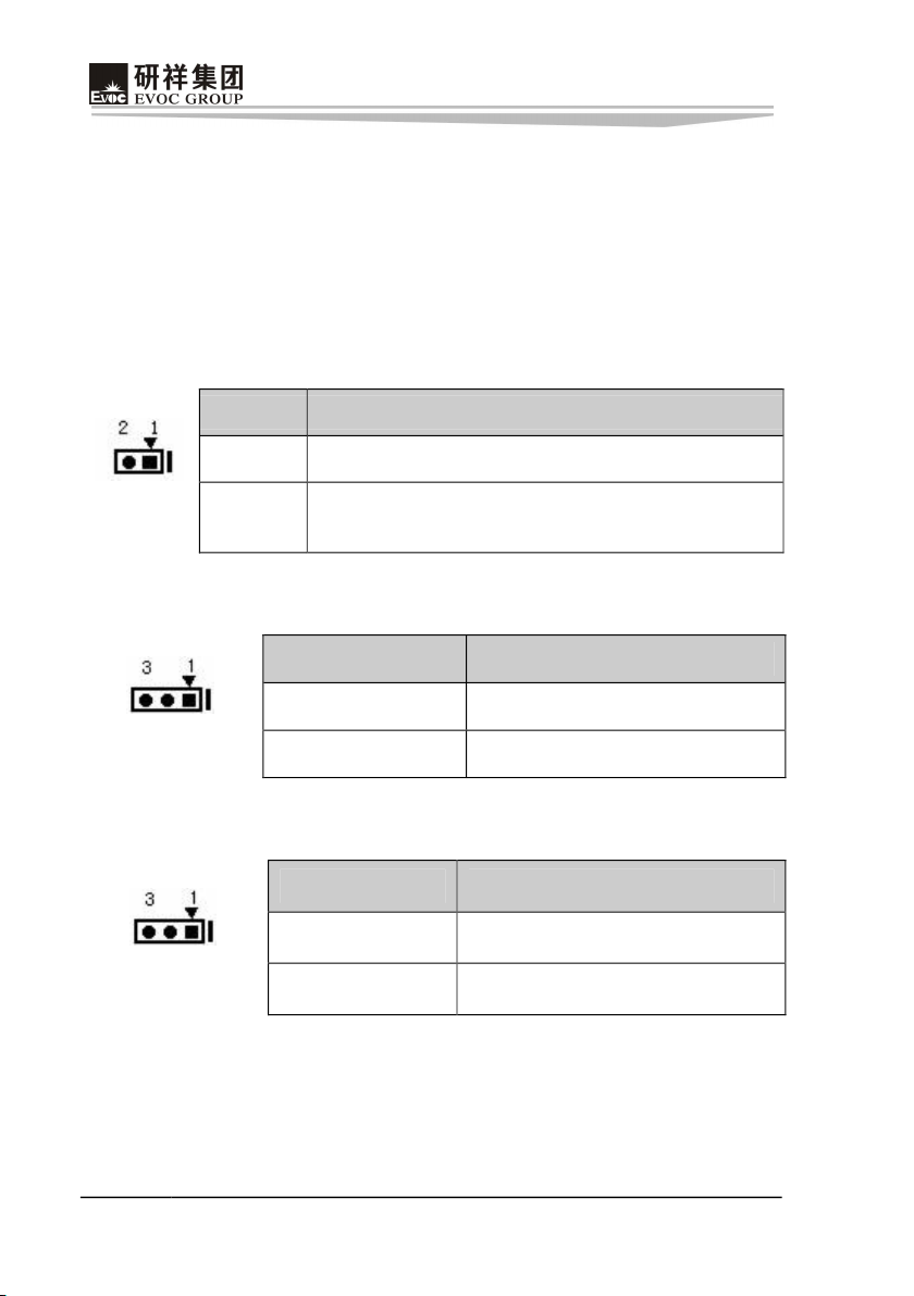
JCC1:Clear/Keep CMOS Setting
By changing the status of the jumper cap of CMOS to realize this function. If the
systemcannotstartupnormallyduetoimproperBIOSsetup,usersmaytrytoclear the
contents of CMOS to restore the default value of the system parameters andrestart
thesystem.
Setup Function
12Open Normal(Default)
JCC1 12Short Clear the contents of CMOS, all BIOS setting will
restoretofactorydefaultvalues.
JCF1:CFCard OperatingVoltageSelection
Setup Function
12Short +3.3V (Default)
JCF1 23Short +5V
JLCDB1:LVDS BacklightVoltageSelection
Setup Function
12Short +12V(Default)
JLCDB1 23Short +5V
Indice
Altri manuali EVOC Computer a scheda singola


