FIPA GS01.004 Manuale utente

Operang instrucons
Sensor-relay-switchboxes
GS01.004
GS01.006
GS01.008
GS01.012

EC Declaraon of Conformity
In accordance with the EC Machinery Direcve 2006/42/EC of May 17, 2006, Annex II B
We
FIPA GmbH
Freisinger Str. 30
85737 Ismaning
hereby conrm that the products:
GS01.004
GS01.006
GS01.008
GS01.012
do not contain any toxic substances that are specied in the RoHS Direcve 2011/65/EU.
Conformity with RoHS Direcve 2011/65/EU is conrmed!
Ismaning, January 2018
Place and date
Rainer Mehrer,
CEO
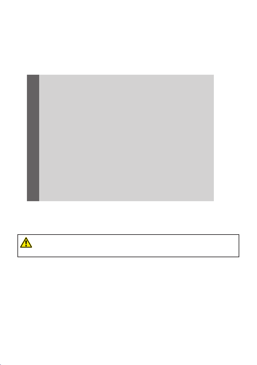
Table of Contents
1. INTRODUCTION 4
2. SAFETY 5
3. TRANSPORT INSTRUCTIONS 5
4. STORAGE 6
5. INSTALLATION 6-11
6. TECHNICAL DATA 12
7. MAINTENANCE INSTRUCTIONS 13
8. OTHER DOCUMENTS 14
SYMBOLS
Aenon! Please observe without fail!
Failure to comply can cause damage to the component, damage to the connected
system/machine or personal injury.

Sensor-relay-switchboxes
4
1. INTRODUCTION
The GS01.004, GS01.006, GS01.008 and GS01.012 sensor switchboxes are used for AND-operaon of
sensor signals to save on digital inputs for robot control systems, for example. They dier only in the
number of sensor inputs; the basic structure is idencal for all sensor switchboxes.
The connected sensors may be of PNP or NPN type, or they may be potenal-free; reversed sensor
logic can also be corrected. In addion, various sensor types can
be mixed in one AND-operaon group. The connected output signals can also be of PNP or NPN type.
The sensor switchbox is supplied pre-assembled and safely packaged.
The operang instrucons include a descripon of the safety regulaons, installaon and mainte-
nance, together with the technical data. If you have further quesons about the sensor switchbox,
please contact our Technical Sales department (+49 89 962489-0).
FIPA consistently strives to develop and improve the design and construcon of its vacuum compo-
nents. We therefore reserve the right to make changes to the design and technical features without
noce.
All of the informaon in these operang instrucons corresponds to the features at the me of pub-
licaon. Prinng errors are excepted.
Rainer Mehrer,
Managing Director
The design and construcon of the sensor switchbox may not be altered under any
circumstances without the consent of FIPA GmbH. Only original
FIPA accessories and spare parts may be used.

5
Sensor-relay-switchboxes
2. SAFETY
Read these operang instrucons carefully before inial commissioning and observe the following
safety regulaons. The sensor switchbox may be operated and maintained only by personnel who
have read these operang instrucons and fully understood their content. Append these operang
instrucons to your general operang instrucons for the system/machine as a whole.
A visual inspecon must be carried out before commissioning. The sensor switchbox must not show
any obvious signs of damage. It must be free from moisture, dust and dirt.
2.1. SOURCES OF DANGER
> The device must not be operated or maintained by personnel who are under the inuence of
alcohol, medicaon that impairs percepon such as sleeping tablets or strong painkillers, or
other drugs. Other condions such as circulaon problems and dizziness are also criteria for
prohibing personnel from operang this system.
> The device must not be operated or maintained by personnel who have not been trained or
have not read and understood this introducon.
> The operator is responsible for ensuring that no personal injuries can be caused when working
with the device.
> The sensor switchbox must never be tampered with.
3. TRANSPORT INSTRUCTIONS
During transport it must be ensured that the sensor switchbox is protected against temperature and
moisture.
3.1. PACKAGING
The sensor switchbox is packed in a cardboard box.
3.2. UNPACKING
Open the cardboard box carefully (do not use sharp objects!). Take the switchbox out of the card-
board box and ensure than none of the small parts that are included in the box is lost.
4. STORAGE

Sensor-relay-switchboxes
6
Storage condions for the sensor switchbox:
> Room temperature of 0 - 40°C
> Humidity of 40 - 60%
> Undamaged packaging
5. DESCRIPTION OF ASSEMBLY
The sensor switchbox must be correctly wired and assembled under de-energized condions. It must
not be assembled underwater or at temperatures above 60°C.
The sensor switchbox is used for AND-connecon of sensor signals, to save on inputs for robot con-
trol systems, for example. The basic structure is idencal for all sensor switchboxes; they dier only
in the number of sensor inputs.
Unlike a series circuit, a separate signal is fed through several miniature relays, each of which is ac-
vated by a sensor. Each sensor must therefore feed the (small) relay coil, but not all of the following
sensors. There are no voltage drops at PN transion points.
> Addional tool: Screwdriver
5.1. FITTING CABLE GLANDS
With the small GS01.004 switchbox, cable glands can only be ed on the top and boom. With the
larger GS01.006/GS01.008/GS01.012 switchboxes, all four sides can be connected.
94
65
56,7
R7,5
79
50
Kopf- /Fußseite Anschluss
mit M16 oder M20
Linke und rechte Seite Anschluss
mit M16 oder M20
(GS01.006; GS01.008; GS01.012)
5.2. ATTACHING THE SENSOR CABLES
Note: In the following illustraons, only the circuit board of the sensor switchbox is shown in the

7
Sensor-relay-switchboxes
interests of clarity.
First, t the sensor cables. Each sensor input consists of a terminal
for +24 VDC (brown), sensor signal IN (black) and earth (blue).
Important: The circuit board terminals do not require soldering, screwing or insulaon stripping.
Remove the outer insulaon of the sensor cable only!
The colored insulaon on the individual wires must not be removed, but the uninsulated wires are
inserted into the upper, extended part of the slot once the corresponding push-buon actuator has
been pulled up. Pushing down the orange push-buon actuator causes two contact pieces to cut
through the wire insulaon, creang a conducve connecon between the wire and the terminal.
5.3. SETTING THE SENSOR TYPE
Next, set the type of the sensors used by connecng two of the three contact pins behind the con-
necon terminal with a jumper.

Sensor-relay-switchboxes
8
The following illustraon shows the labelling on the circuit board(s), in parcular the labelling on the
jumper contacts.
In the following example, six sensors have been connected. The rst sensor and the third to the sixth
sensor are PNP type, while the second is an NPN sensor:
The jumpers are inserted in such a way that the center contact pin is connected with the le (NPN)
or the right (PNP) contact pin in each case.
5.4. CREATING GROUPS
The connected sensors can be combined to form one or more groups connected by an AND-opera-
on. The sensor switchboxes allow any group formaon.

9
Sensor-relay-switchboxes
In the example, the rst four and the last two sensors are to be connected by an AND-operaon.
Groups I and II are formed.
First the type of output signal must be established. This is determined by the design of the digital
inputs on the control system to which the switchbox is connected.
If there are PNP inputs (as with most European manufacturers), the output signal on the
sensor switchbox must be PNP type, in other words it must make a conducve connecon
between +24 VDC and the input.
If there are NPN inputs (as with most Asian manufacturers), the output signal on the sen-
sor switchbox must be NPN type, in other words it must make a conducve connecon
between the input and earth.
The type must be set for each sensor group, although usually the same sensor type is set, as the
same control system is involved.
Sensor-relay-switchboxes
10
To do this, a jumper is connected to the rst relay of the group:
The other contact pins above the relay remain free!
(In the example, the sensor switchbox is connected to a control system with PNP inputs. For a control
with NPN inputs, the le and center contact pins would have to be connected.)
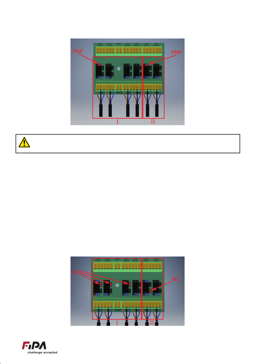
The next step is to make the connecon for the AND-operaon itself. Either the normally closed
contact or the normally open contact of a relay must be connected to the common switching contact
of the next relay, with the excepon of the last relay in a group.
In the example, all of the sensors in group I are normally open contacts.
The two sensors in group II, on the other hand, are normally closed contacts, i.e. they should detect
if the two signals are not present. (This is oen the case with through-beam light barriers, for ex-
ample.)
The jumpers are inserted as follows:
Questo manuale è adatto per i seguenti modelli
3
Indice


