Sigma_XT_signs_m3.5.docx Page 2 of 14
Contents
1. Introduction............................................................................................................................................ 3
Sign Locations........................................................................................................................ 3
Local Control Stations (LCS) .................................................................................................... 3
External Devices..................................................................................................................... 3
Cable Penetrations and Terminations ....................................................................................... 3
2. Mounting................................................................................................................................................ 4
Internal Signs......................................................................................................................... 4
External Signs ........................................................................................................................ 4
3. Power and Data Connections ................................................................................................................... 5
Connecting Signs with RS485 Serial ......................................................................................... 5
3.1.1. Connecting up to 3 Signs .......................................................................................... 5
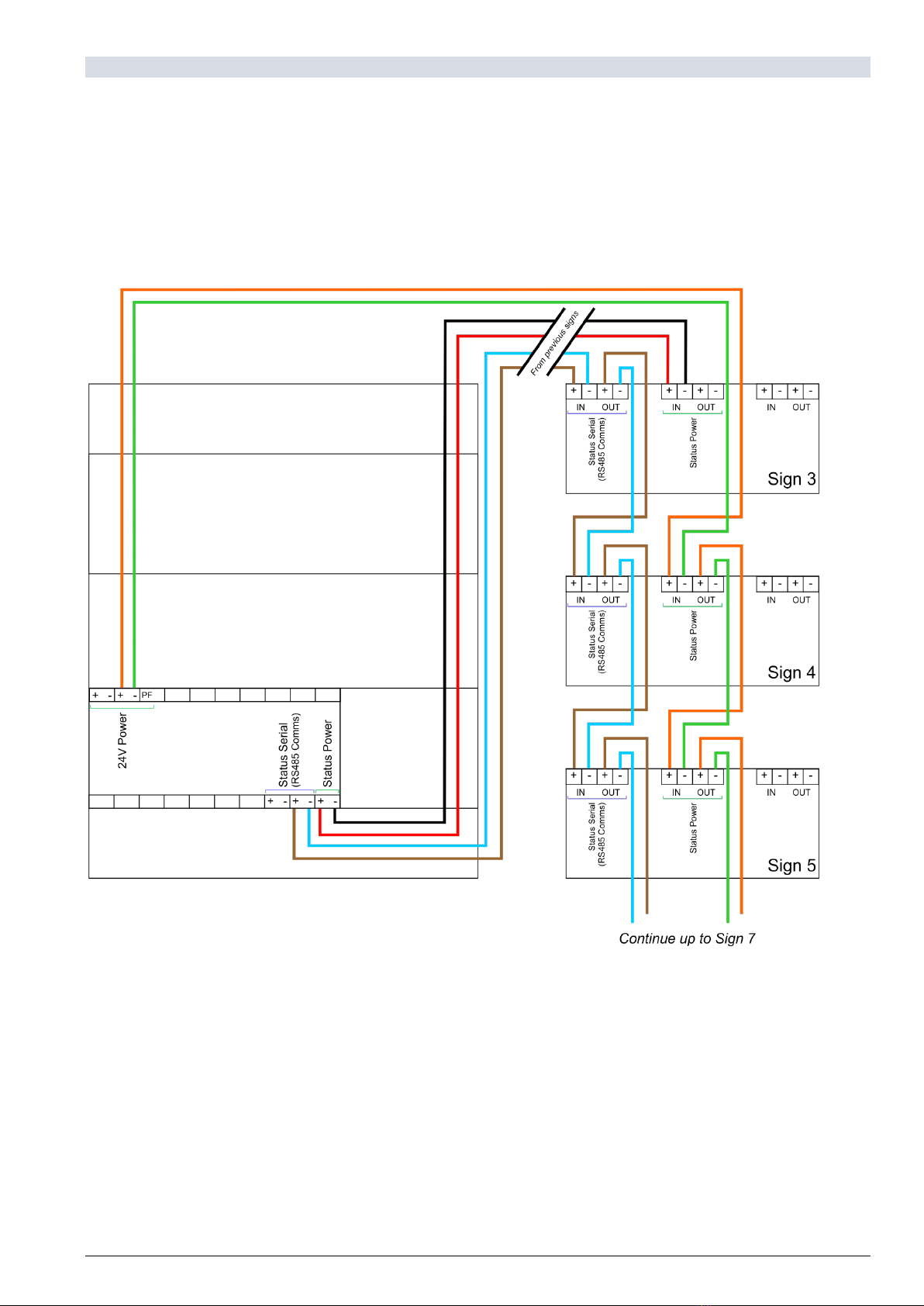
3.1.2. Connecting more than 3 Signs .................................................................................. 6
4. Connection of Local Control Station (LCS)................................................................................................. 7
Power and Data Connection .................................................................................................... 7
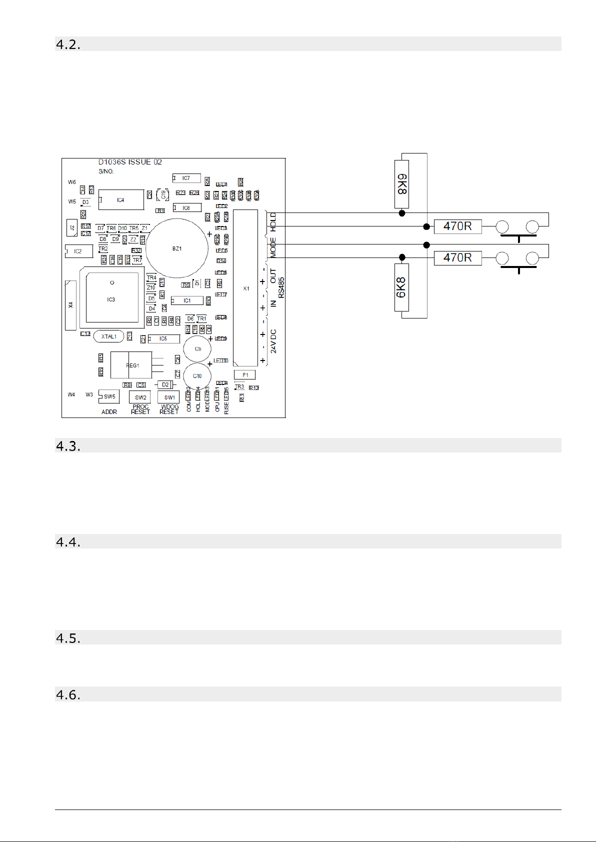
Connection to Hold and Mode inputs ....................................................................................... 8
Mode input............................................................................................................................. 8
Hold input.............................................................................................................................. 8
Mode select keyswitch ............................................................................................................ 8
Manual release ....................................................................................................................... 8
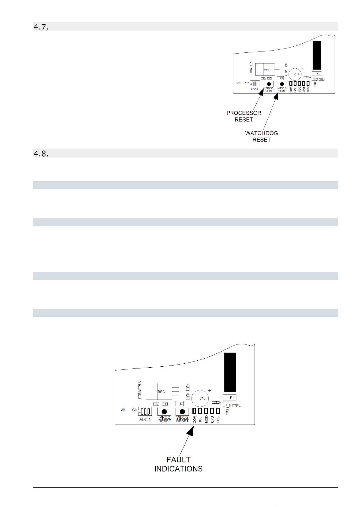
Processor and Watchdog Reset Switches ................................................................................. 9
Internal fault indications ......................................................................................................... 9
4.8.1. COM ........................................................................................................................ 9
4.8.2. LOCK OFF ................................................................................................................ 9
4.8.3. MOD........................................................................................................................ 9
4.8.4. FUSE ....................................................................................................................... 9
5. Setting up the Devices .......................................................................................................................... 10
Addressing Devices............................................................................................................... 10
Assigning Sign Function ........................................................................................................ 10
6. Adding Devices to FIP Programming....................................................................................................... 11
Adding / Removing Devices at the FIP ................................................................................... 11
7. Alternative Sign Arrangements............................................................................................................... 12
Mimic Signs / Connecting more than 7 Signs .......................................................................... 12
Alternative Arrangement of STATUS SERIAL (RS485) Circuit. .................................................. 13
8. Troubleshooting.................................................................................................................................... 14
9. Specifications........................................................................................................................................ 14