fischertechnik COMPUTING ROBO TX ElectroPneumatic Manuale utente
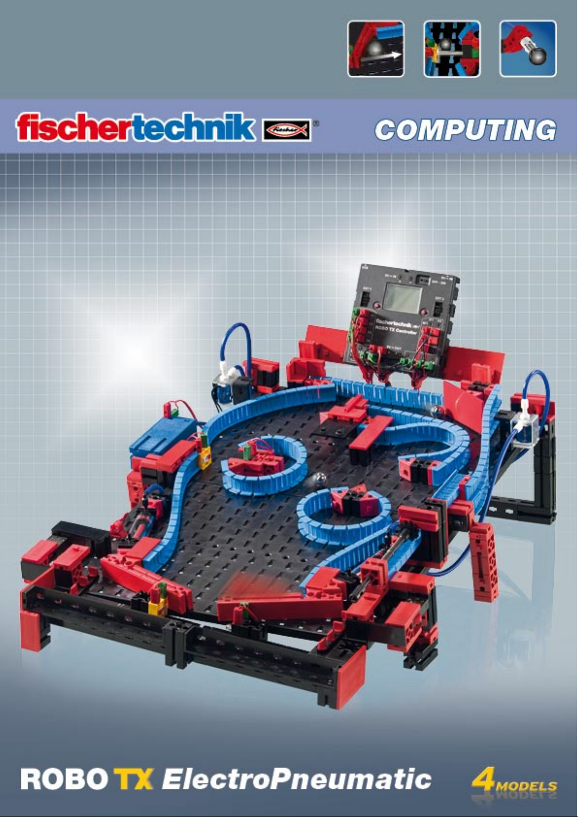

ROBO TX ElectroPneumatic
COMPUTING
2
Contents
Welcome to the fischertechnik Computing World 3
About this Activity Booklet 3
History 4
Principles of pneumatics 4
Producing motion with air 4
Generating and storing compressed air – diaphragm pump as compressor 5
Switching compressed air – solenoid valves 6
Interaction of electrical and pneumatic circuits 6
ROBO Pro control software 7
ROBO TX Controller 7
Compressed air motor 8
Programming 9
Color sorting robot 10
Sensors 10
Sensors and actuators 11
Color recognition subprogram 12
Ball obstacle course with vacuum picker arm 13
Variables 14
Pinball machine 15

ROBO TX ElectroPneumatic
COMPUTING
3
Welcome to the fischertechnik Computing World
Hello!
Congratulations on your purchase of the ROBO TX ElectroPneumatic con-
struction set from fischertechnik. We promise you that your interest will be
rewarded. Because with this construction set you can conduct many interesting experi-
ments and solve exciting tasks.
This digital activity booklet accompanies you step for step as you try out your fischertechnik models. It
contains important tips and valuable additional information for conversion and optimization. At the end
you will be able to control and program various electro-pneumatic models with the ROBO TX Control-
ler. We start with simpler things initially to ensure you have fun right from the very beginning. With the
knowledge you gain you can then meet the challenge of the next task - and so forth - step for step.
So don't be timid, we will plunge into the fischertechnik Computing World together and then go on to
more complex tasks.
Now we wish you a great deal of fun and success experimenting with the ROBO TX ElectroPneumatic
set.
Your team from
About this Activity Booklet
This PDF Activity booklet has a few features not present in the printed booklet. Most are similar to those
you may already be familiar with from the Internet. But sometimes they can also do more.
Purple text
▯
This shows you information on the term itself when you roll over it with the mouse.
Underlined blue text:
▯
This actuates a function when clicked - for example starting the ROBO Pro help.
▯ ROBO Pro Symbol:
This is always located in the vicinity of tasks. This makes sense, because as soon as you click on it a suitable
example program opens with a possible solution.
All example programs are listed under C:\Programs\ROBOPro\Example programs\ROBO TX Electro-
Pneumatic.
test only.rpp

ROBO TX ElectroPneumatic
COMPUTING
4
History
EN
Compressed air is one of the oldest forms of energy. Nearly 2500 years ago soldiers
built military equipment, which used compressed air to shoot projectiles such as balls
or spears.
Ctesibius from Alexandria in Egypt, (* 296 B.C. in Alexandria, † 228 B.C.), was a Greek
engineer, inventor and mathematician, who lived during the first half of the third cen-
tury before Christ and built weapons operated by compressed air.
It is therefore no wonder that the word "Pneumatic“ was taken from the Greek word
"pneuma“, which means "air“.
The first compressor was a bellows. In blacksmith shops in the middle ages and far
later, right up to today's modern industrial era, bellows have been used to increase the
temperature of a fire.
A
Today pneumatics play an essential role in modern industry. Pneumatically driven ma-
chines and automation equipment can be found everywhere. For example, on assem-
bly lines various parts are put together to form assemblies and the function is checked;
goods are sorted and packed.
Principles of pneumatics
Air can be used for different purposes in technology. For example wind drives gigantic
windmills to generate electrical power. Pneumatics uses air to generate motion and
transfer forces.
You are certainly familiar with at least one pneumatic tool - the air pump for your
bicycle tires. It is designed using the physical and technical principles of a cylinder, as
introduced in this construction set, for example using a compressor to generate com-
pressed air.
Producing motion with air
A number of pneumatic cylinders are included in the ElectroPneumatic construction
set. You need one of them for the first experiment.
Pneumatic cylinder from fischertechnik
The piston rod with piston can
move and is sealed along the cylin-
der wall by gaskets.
If you blow air into the cylinder
through connection A, the piston
moves.
Piston rod with
piston and spring
Hose connection A
Hose connection B
(not used)
Industrial cylinder

ROBO TX ElectroPneumatic
COMPUTING
5
The air moves this cylinder in one direction only. It is returned to its initial position by the force of a
spring. Such cylinders are called "single acting cylinders".
Note:
The connection you use to move out (extend) the piston is designated "A"; the piston is pulled back (re-
tracted) with the aid of a spring.
Air can be compressed
Anyone working with pneumatic equipment today should know something about the physical properties
of air. You can use a little test for this purpose:
Pull the red piston rod in the cylinder all the way out. Then hold connection A shut with your finger.
Now release the piston rod. What can you observe?
The piston rod is pulled back only a short distance by the spring.
Result:
The air in the cylinder is pressed together (compressed) preventing the piston rod from moving. The
more air compressed, the greater the air pressure in the cylinder. This pressure can be measured with a
pressure gage or also calculated. The unit of measure for pressure is ”bars” or ”Pascals”
You can remember the following equation for this:
Pressure = force/area or p = F/A
From this equation you can see that the pressure depends on the force exerted on a round surface in the
cylinder.
Generating and storing compressed air – diaphragm pump as compressor
The diaphragm pump included in the construction set supplies the compressed air required for you to
control the individual models. In industrial circles this is known as the compressed air source.
Mode of operation:
A diaphragm pump consists of two chambers
separated by a diaphragm (membrane). In one
chamber the resilient diaphragm is moved up
and down by a piston or cam. During the down-
ward stroke the diaphragm is pulled back and
air is pulled into the second chamber through
the inlet valve. When the piston moves up, the
diaphragm presses the air out of the pump head
through the outlet valve.
Note:
The pressure generated by the compressor is approx. 0.7 to 0.8 bars. The diaphragm pump is mainte-
nance-free.
Circuit diagram of single
acting cylinder
Pressure gage for
measuring air pressure
Compressor
Circuit diagram of
compressed air source
Piston
Cylinder
Diaphragm
Inlet/outlet valve
Cover
Crank drive
ROBO TX ElectroPneumatic
COMPUTING
6
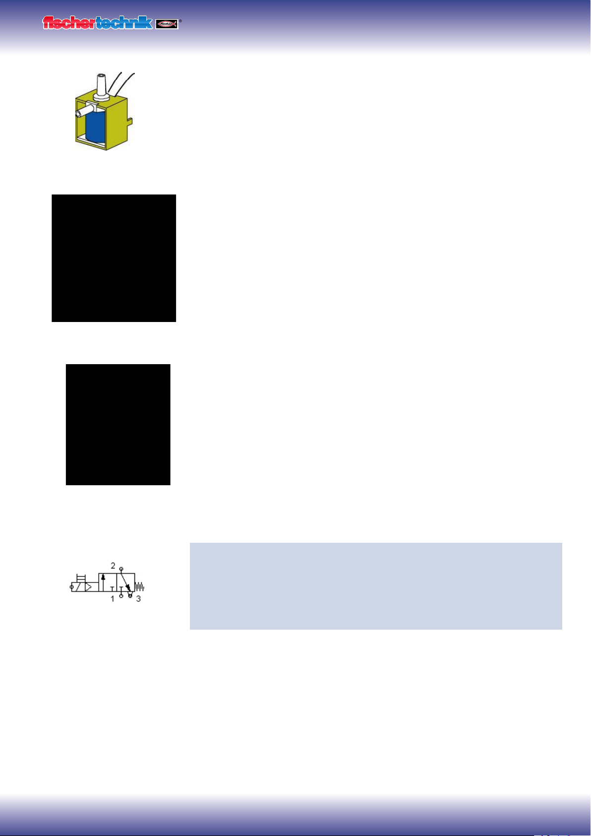
Switching compressed air – solenoid valves
In pneumatics the purpose of a valve is to control the flow of air to the pneumatic cylin-
der so that the cylinder either extends or retracts. The valve can be actuated either by
hand, pneumatically or electromagnetically as on your technical models.
Technical data on valve: 3/2-way valve, 9V DC/130 mA
3/2-way means that the valve has three connections and two switching states.
Note:
When connecting the valve to the power source or to the ROBO TX Controller ensure
that the polarity is correct.
Brief technical explanation:
Applying a voltage to the coil (1) creates a magnetic field which pulls down core (2).
The valve opens and the air flows from connection "P" through connection "A" to the
cylinder. When voltage is not applied, the core is pressed upward by the spring (3) and
the valve is closed.
When the valve is closed, connection "A" is connected to the vent "R". This is important,
to allow the air to escape from the cylinder.
The connections are always designated as follows in pneumatics:
P = Compressed air connection
A = Connection to cylinder
R = Vent
Interaction of electrical and pneumatic circuits
Task:
Actuate a solenoid valve to extend a single acting cylinder. The cylinder should
extend when the operator closes a switch. As long as the switch is closed, the
cylinder should remain extended. When the switch is returned to the initial posi-
tion, the pressure of the spring should cause the cylinder to retract.
Engineers frequently use symbols to show such tasks. One circuit diagram shows the
electrical part and one the pneumatic part or stage.
3/2-way valve
P
A
R
(1)
(2)
(3)
P
R
A
Circuit diagram of a 3/2-way valve

ROBO TX ElectroPneumatic
COMPUTING
7
In the illustration the electrical part is on the left and the pneumatic stage on the right.
The electrical part consists of a +9V power source, a pushbutton and the valve coil
(electromagnet). The pneumatic stage consists of the compressed air source, the valve
and the cylinder.
Note:
Since the magnetic coil and valve form one unit, they are shown using the same sym-
bol. This clearly shows that the coil and valve belong together.
The two figures below show the circuit in the non-actuated state, in the figure on the
right with the button pressed. The figure on the right clearly shows the flow of electric-
ity as well as air.
ROBO Pro control software
Control logic with ROBO Pro software and ROBO TX Controller
In addition to its mechanical construction, the unit requires the control logic, software
for the PC and an interface ( ROBO TX Controller) to convert the software commands
into signals which the machine can execute.
The ROBO Pro control software has a simple graphical programming interface which
allows you to create programs without having to learn a programming language.
For the ROBO TX ElectroPneumatic construction set you need ROBO Pro version
3.1.3 or higher. If you have an older version of the software, it will be automatically
updated when you install the ROBO TX ElectroPneumatic CD.
ROBO TX Controller
The ROBO TX Controller is the most important component in the model. It controls
the actuators (motors, lights & valves) and evaluates information from the sen-
sors. For this purpose the ROBO TX Controller has numerous connections
for connection to the components. The instruction manual for the ROBO
TX Controller describes which components can be connected to which con-
nections and the functions of the connections.
A special feature is the integrated Bluetooth interface. It allows you to complete a
wireless link between your PC and the ROBO TX Controller. Or to connect a number
of controllers with one another. You can define how the controller interacts with the
individual components and what they are to do in detail in the program you write with the ROBO Pro
software.
+9V
T1
V1 V1
0V
A1
A
P R
Circuit diagram - electrical, pneumatic stage
+9V
T1
V1 V1
0V
A1
A
PR
+9V
T1
V1 V1
0V
A1
A
PR
Circuit diagram - non-actuated position Circuit diagram - button pressed
Program example with
symbolic commands
ROBO TX ElectroPneumatic
COMPUTING
8
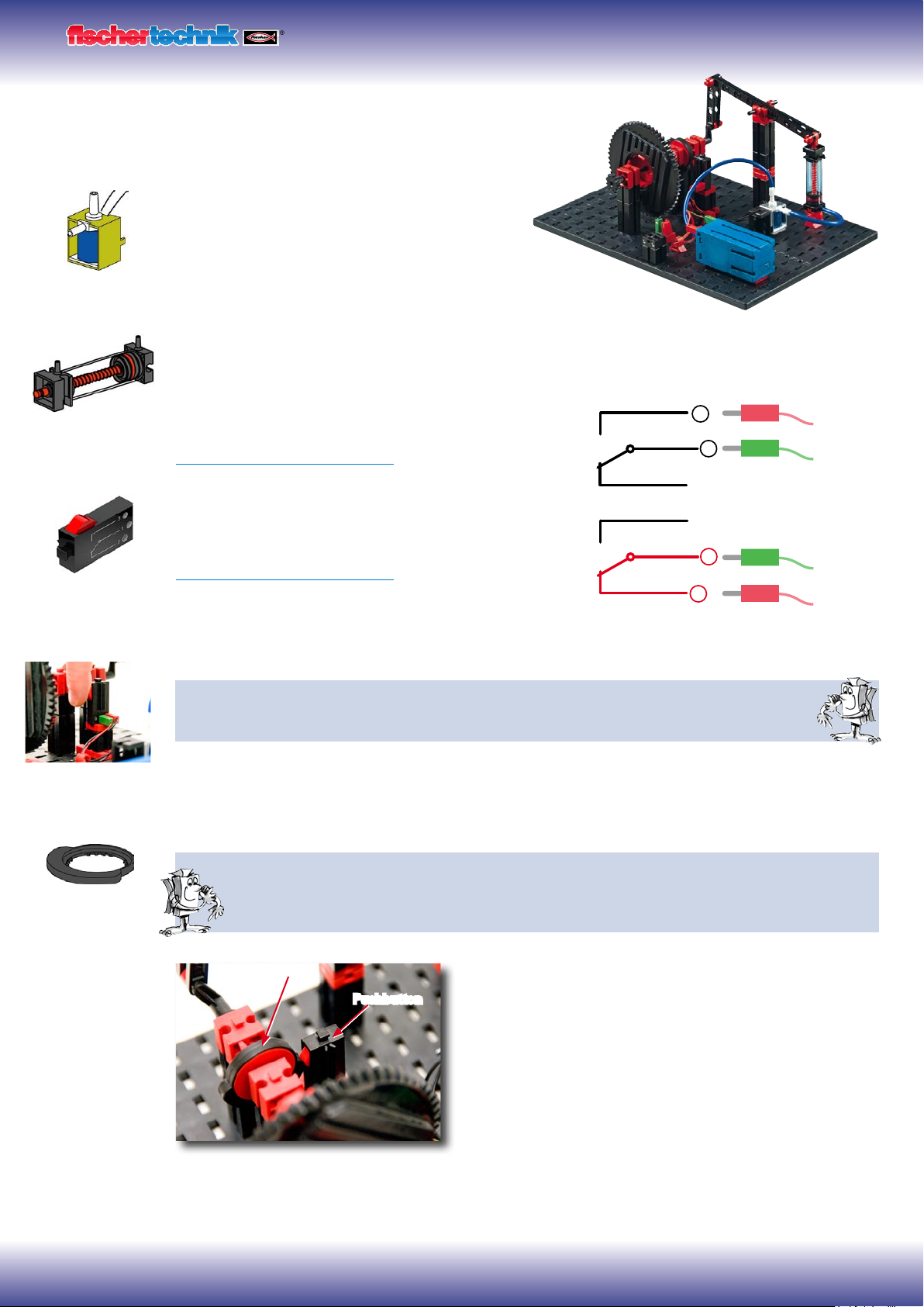
Compressed air motor
For your first model, build the "compressed air motor" as
described in the assembly instructions. A compressed air
or pneumatic motor functions similar to a steam
engine. It has a cylinder, a piston, an intake and
an outlet. However, compressed air serves as the
"propellant" instead of hot steam. For the first task install
the button so that you can press it with your hand.
Technical information on pushbutton.
The pushbutton has three connections or terminals. Depending on the application you can use the push-
button ....
... as a "normally open switch":
By connecting terminals 1 and 3.
When the pushbutton is pressed: Electricity flows.
When the pushbutton is not pressed: Electricity does not flow
... or as a "normally closed switch":
By connecting terminals 1 and 2.
When the pushbutton is pressed: No electricity flows.
When the pushbutton is not pressed: Electricity flows.
Wire the electrical components as described in the assembly instructions in circuit diagram A.
Task 1: Manual control with pushbutton.
Press the button and observe the model. What makes the wheel turn and how?
As you can see, each time you press the button the solenoid valve switches and the cylinder extends.
This causes the wheel to rotate half a turn. When you release the button, the wheel rotates another half
turn. This is accomplished by the return spring in the pneumatic cylinder.
Task 2: Control with switching plate.
Turn the pushbutton to the installation position specified. Instead of pressing the button manually, it
is now actuated by a switching plate. How will this affect the model?
It is necessary to switch the valve on and off at the right time.
Then the wheel will rotate continuously.
Important! Adjust the switching plate so that the pushbutton
switches the valve exactly when the crank is in the top-most
or bottom-most position.
For the next task install the ROBO TX Controller in the model
and wire the electrical components as described in circuit B in
the assembly instructions.
Switching plate
Pushbutton
Pneumatic cylinder
Pushbutton
3
1
2
3
1
2
3/2-way valve
Switching plate
ROBO TX ElectroPneumatic
COMPUTING
9
Task 3: Testing the model with the ROBO TX Controller
Connect the ROBO TX Controller to the power supply and switch it on. Con-
nect the ROBO LT Controller to the PC. Then start the ROBO Pro software.
Activate the "Test" button. The operating display appears to test the control-
ler and the connected sensors and actuators. Click with the mouse pointer
on Output M1 - right and then Output M2 - right. Observe what happens at Input
I1.
The compressor at Output M1 starts running and produces compressed air for the cyl-
inder. If M2 is switched on, the solenoid valve is actuated and the piston in the cylinder
extends. At Input I1 a check set when the connected pushbutton is closed.
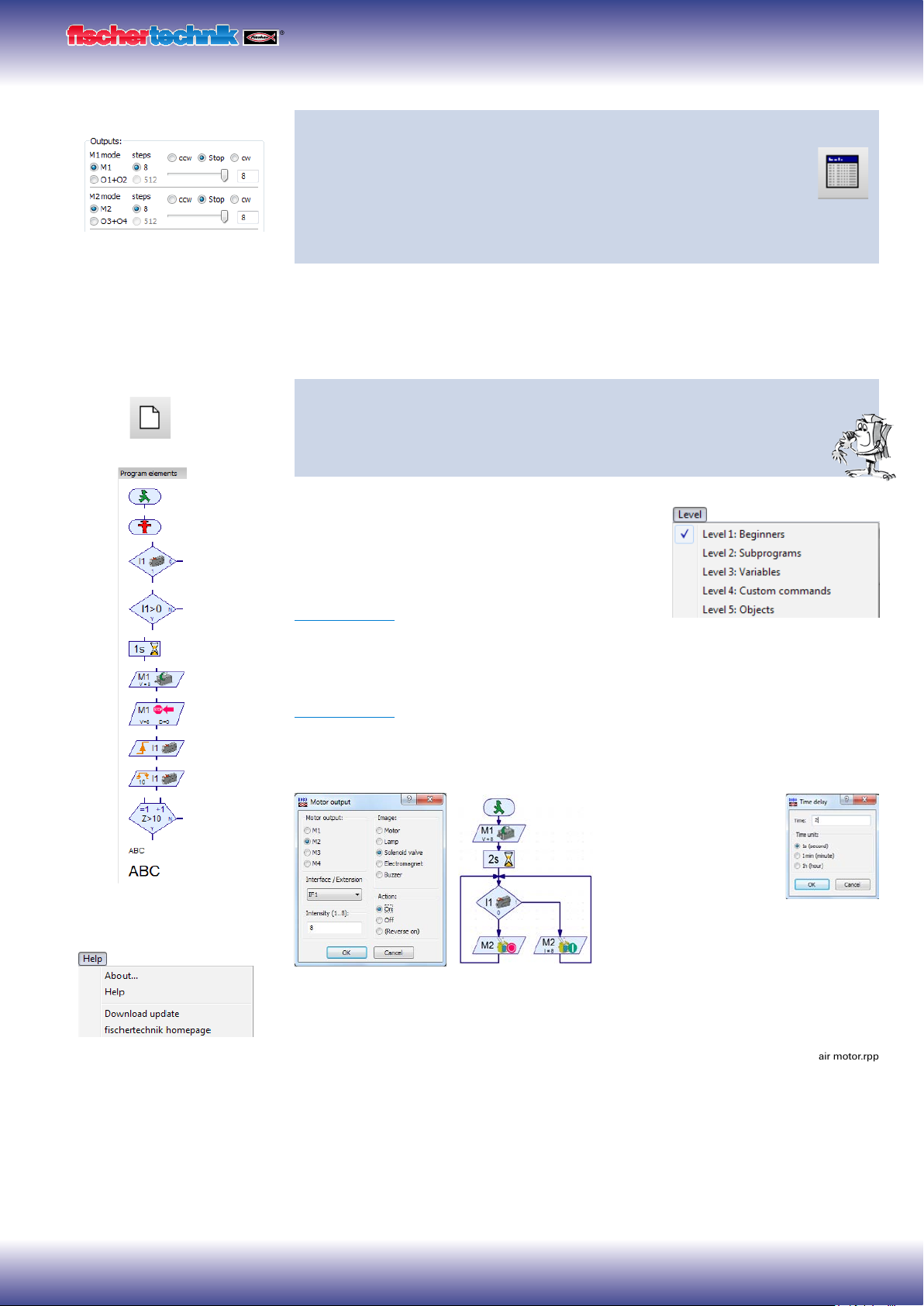
Programming
Task 4: Program control with ROBO Pro - Level 1
ROBO TX Controller takes over actions in task 3 using program. Here the
switching state of pushbutton (I1) is checked and the information, "closed/
open" used to control the valve and cylinder.
The operating display can be cleared with the "New"
button. In the "Level" selection window switch to level
1.
All the commands required for this task are present in
the "Element group" selection window. However the
ROBO Pro help is also very valuable here.
Each program always starts with the "Little green
traffic light man". Then the individual program commands such as "Motor on" or "Time
delay" can be entered. The symbols can be moved to the operating display with the
mouse using the drag and drop feature. Information on the commands used is given in
ROBO Pro help Chapter 3.
Use the program from the following program structure:
Click with the right
mouse button on the
desired symbol; an inter-
active window appears
in which you can make
various settings, e.g. set
the time, actuator, etc.
You can call a finished example program for this task with this symbol.
New program
Important! You can get help
under the menu point
or by clicking the right mouse
button on the program element
in the "Element window"
compressed air motor.rpp

ROBO TX ElectroPneumatic
COMPUTING
10
After finishing the program, you can start it with the button "Start program in online
mode". The individual program steps are then performed. Since you have programmed
a continuous loop, it is also necessary to stop it, when you are finished. For this pur-
pose use the button "Stop all running programs".
It may be necessary to readjust the switching plate when operating the compressed air
motor with the ROBO TX Controller, to get the motor to run "smoothly". You can do this
by trial and error.
It is possible to transfer the program to the ROBO TX Controller. This can be accom-
plished with the "Download" button. The interactive window appears to enter the vari-
ous parameters.
Start program: The program can be started immediately after
transfer or after pressing a button. Information is given in
ROBO Pro help Chapter 3.7.
Color sorting robot
The color sorting robot model is
designed to sort parts automati-
cally according to their color. Build
the model according to the assem-
bly instructions and wire the electrical and
pneumatic components according to the circuit
diagram. During assembly pay attention to accuracy when
installing the parts, connecting the hoses and wiring the electri-
cal components. This eliminates the need for trouble-shooting when you put the model
into operation.
Sensors
With this model you become familiar with new components such as those used in
industrial equipment. This includes the vacuum picker arm with suction cup, the two-
cylinder vacuum generator, the optical color sensor and the light barrier with phototran-
sistor and light source.
Optical color sensor
Color sensors are used frequently in automation technology. This is done, for example,
to examine the color or the color imprint to ensure that the correct components are
installed. The fischertechnik color sensor transmits red light, which is reflected with
different strength from different colored surfaces. The quantity of reflected light is
measured by the phototransistor and output as a voltage between 0 V and 10 V. A type
of "darkroom" is built into the sensor in this model to prevent excessive light scatter. An
opening is provided for the sensor. The part to be measured can be positioned on top
of this opening.
Start program in online
mode
Stop
all programs in progress
Download program for ROBO TX Controller
Indice
Altri manuali fischertechnik Robotica

fischertechnik
fischertechnik ROBOTICS TXT Discovery Set Manuale utente

fischertechnik
fischertechnik Robotics BT Beginner Manuale utente

fischertechnik
fischertechnik Early Coding Manuale utente

fischertechnik
fischertechnik COMPUTING ROBO MOBILE SET Manuale utente

fischertechnik
fischertechnik MR2 Manuale utente

fischertechnik
fischertechnik Smart Robots Pro Manuale utente

fischertechnik
fischertechnik ROBOTICS TXT Smart Home Manuale di installazione e funzionamento

fischertechnik
fischertechnik Mini Bots Manuale utente

fischertechnik
fischertechnik ROBO Manuale utente

fischertechnik
fischertechnik PROFI Dynamic XXL Manuale di installazione e funzionamento


