
Fleece Duramax PowerFlo LB7 Manuale utente

SUBJECT: 2001 –2004 LB7 Duramax PowerFlo Lift Pump
FPE-2021-58
July, 2021
FITMENT: 2001–2004 LB7 Duramax equipped Chevy/GMC trucks
KIT P/N: FPE-34809
EST. INST. TIME: 3 hours
TOOLS REQ’D: 1/2” and 3/8” fuel disconnect tools (included), 15mm deep socket and ratchet, 8 mm socket and
ratchet, hammer, chisel or drift.
KIT CONTENTS:
Item
Description
Qty
1
PowerFlo lift pump
1
2
Chassis harness
1
3
Tank flange seal
1
4
Level sender float
1
5
3/8” Fuel line disconnect tool
1
6
1/2" Fuel line disconnect tool
1
WARNINGS:
•Fuel system, including fuel tank, fuel supply, and fuel return lines must be clean before installation.
•Use of this product may void or nullify the vehicle’s factory warranty.
•The purchaser and end user releases, indemnifies, discharges, and holds harmless Fleece Performance Engineering, Inc.
from any and all claims, damages, causes of action, injuries, or expenses resulting from or relating to the use or installation
of this product that is in violation of the terms and conditions on this page, the product disclaimer, and/or the product
installation instructions. Fleece Performance Engineering, Inc. will not be liable for any direct, indirect, consequential,
exemplary, punitive, statutory, or incidental damages or fines cause by the use or installation of this product.
3
1
4
2
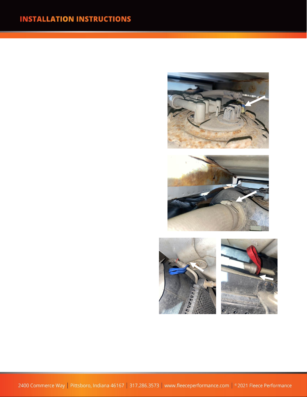
STEP 1: Ensure you have 1/4 tank or less of fuel in the
fuel tank to allow for the tank to be easily lowered
and maneuvered. Leave enough fuel in the tank to
allow for the pump to draw fuel in immediately once
installed.
STEP 2: Disconnect the electrical connector from the
fuel level sending unit.
STEP 3: Loosen the 8mm hose clamp on the filler
neck and remove the filler neck from the tank.
STEP 4: Remove the fuel lines at the front of the tank,
and at the fuel cooler with a 3/8” and 1/2” fuel line
disconnect tool.
NOTE: Thoroughly clean the fuel line connection prior
to removal with a rust preventative such as WD-40 or
PB Blaster. Clean the connection with compressed air
or a pick to ensure debris does not become lodged in
the fuel line during removal. Have a drain pan or
bucket ready to capture the fuel that will drain from
the system when the lines are disconnected.
PROCEDURE:

STEP 5: Place a transmission jack or floor jack below
the fuel tank and lightly support it. Remove the tank
straps using a 15mm deep socket. With the tank
straps removed, carefully support the fuel tank and
lower it down to the ground.
STEP 6: Thoroughly clean off the top side of the tank
around the sending unit to avoid getting any debris
inside the fuel tank when the sending unit is
removed.
STEP 7: Remove the fuel lines at the sending unit
with the quick disconnect tools.
STEP 8: Using a hammer and a chisel or punch,
remove the locking ring by tapping the ring counter
clockwise.
STEP 9: With the fuel lines and retaining ring
removed, clean any remaining debris away from the
sending unit with a vacuum and rag and avoid debris
entering the fuel tank when the sending unit is
removed. Take note of the orientation tab on the
sending unit cap, the new lift pump will orient in the
same manner as the original.

STEP 10: Remove the OE sending unit and sealing
flange from the tank. Discard the original seal ring.
STEP 11: Thoroughly clean the tank surface where
the new lift pump will be installed. Inspect the inside
of the fuel tank for any debris. If any debris is
present, the tank must be cleaned.
STEP 12: Install the new flange seal included with the
lift pump. Slide it up from the bottom of the pump -
sliding it all the way up to the flange. Perform this
step before installing the fuel level float arm.
Install the fuel level float arm onto the lift pump by
gently clipping the arm into the fuel level sensor.
STEP 13: Install the PowerFlo pump assembly into the
tank and reinstall the retaining ring using ahammer
and punch by rotating it clockwise to the fully
engaged position. Ensure proper orientation of the
pump and fitting by aligning the alignment tab on the
lift pump cap with the marks on the fuel tank.
NOTE: Use caution when installing the pump to not
damage the float arm. DO NOT rotate the pump once
installed in the tank, you will damage the float arm or
sending unit –align the pump before you place it into
the tank.

STEP 14: Reconnect the fuel lines to the lift pump
feed and return quick disconnect fittings. Connect
the new wiring harness supplied with the lift pump to
the original OEM harness connector and the other
end to the PowerFlo lift pump.
STEP 15: Route the wiring harness along the frame
rail of the truck to the engine compartment. Route
the harness in a manner that it will not interfere with
any moving parts and retain it with zip ties.
NOTE: Leave sufficient slack on the harness at the
pump end to allow for plugging in the connection
at the pump before raising the tank back up into
position.
STEP 16: Raise the fuel tank back into its mounting
location. Install the fuel tank hangers, reconnect the
fuel lines at the front of the tank by the fuel cooler,
and install the vent tube and tighten the hose clamp.
STEP 17: Complete the wiring harness installation in
the engine bay. Mount or secure the relay. Connect
the orange wire to the driver’s side battery (+) OR to
the Positive terminal for the jump start connection.
Connect the black wire to the driver’s side battery (-).
Route and install the red wire and fuse tap as shown
on the WIRING OVERVIEW and FUSE TAP LOCATIONS
pages.
STEP 18:Add sufficient fuel back into the tank to
submerge the pump bucket.
CAUTION: Never run the pump dry or without fuel in
the tank.
STARTUP : Turn the ignition key to RUN, but do not
start the engine. Verify the lift pump is running and
that there are no fuel leaks. Allow the pump to
prime the system for 20-30 seconds prior to starting
the engine.

WIRING OVERVIEW:
Black Wire –To Battery negative (-) terminal
Orange Wire –To Battery positive (+) terminal
Red Wire –To Switched Ignition (+) in Fuse Block
Black Connectors –To OEM harness and PowerFlo
lift pump
Relay –Provides switched 12v power to the
PowerFlo pump
To OEM harness and
PowerFlo lift pump
Battery (+)
Battery (-)
Switched
Ignition
(+12v)

FUSE TAP LOCATIONS: Any 12 volt ignition source may be used for the fuse tap. Insert the original fuse from the fuse
panel into the second fuse tap terminal. We recommend using the fuse tap in location “IGN E” if available.
Insert the original fuse from the fuse block
into the relay tap below the 5A fuse that is
provided in the fuse tap. Both fuses are
required for the tap and existing circuit to
function properly.
Indice
Manuali Sistema di sollevamento popolari di altre marche


Genie
Genie Z-60/34 Manuale utente

Screen Technics
Screen Technics INTERFIT Vertical Up Lift Manuale utente

Mortuary Lift
Mortuary Lift ULTIMATE 1000 Manuale utente

Custom Equipment
Custom Equipment Hy-Brid 3 Series Manuale di programmazione

Custom Equipment
Custom Equipment Hy-Brid Lifts 2 Series Manuale di programmazione

Hy-Brid Lifts
Hy-Brid Lifts HB-P3.6 Manuale di programmazione


