Fuho IP901 Manuale utente
IP901 User’s Manual
Page 1
IP901-IP-CAM
USER MANUAL

IP901 User’s Manual
Page 2
Cautions
1. Read this user manual before use
2. Keep this user manual accessible
3. Follow instruction
4. Keep this unit away from cleanser
5. Keep this unit dry in ventilation
6. Give way to ventilation outlet
7. Power cord must be fixed properly
8. To avoid damage, unit must not be stuffed or be splashed with something
9. Do not repair this unit on your own
10. Please contact local dealer for the following condition:
a. Power cord damaged
b. Showered unit
c. Failure in operation
d. Unit dropped or cabinet damaged
11. Repairing components must be approved by original manufacturer.
12. Ground wire of outdoor image source must be well connected to the ground to prevent from
thunder attack
13. Power cord and outdoor image source cable should be detached in case of thunder attack
Warning
Only qualified engineer can detach the cover. There is nothing inside for end users.
Cover must not be removed in case of power on.

IP901 User’s Manual
Page 3
CONTENT
1. OUTLINE
1.1 INTRODUCTION ...................................................4
1.2 FEATURE ................................................................5
1.3 ACCESSORY ..........................................................5
1.4 SYSTEM REQUIREMENT ...................................5
1.5 PANELS ...................................................................6
1.5.1 FRONT PANEL ....................................................6
1.5.2 REAR PANEL ......................................................6
2. INSTALLATION
2.1 CABLING ................................................................8
2.2 SURVEILLANCE SOFTWARE ............................11
2.3 ETHERNET FRAMEWORK & CONNECTION .13
2.3.1 PC TO IP-CAM CONNECTION ........................13
2.3.2 INTRANET CONNECTION ...............................16
3. OPERATION
3.1 LivePlayer SURVEILLANCE SOFTWARE ........19
3.1.1 LivePlay SOFTWARE INTERFACE .................19
3.1.2 LivePlayer INTERFACE SETUP .......................21
3.2 IE BROWSER SETUP CAMERA FUNCTION ..29
3.2.1 Web Server AUTHORIZATION ........................30
3.2.2 Status ...................................................................31
3.2.3 View .......................................................................32
3.2.4 System ....................................................................33
3.2.5 Network .................................................................34
3.2.6 Image .....................................................................35
3.2.7 User ........................................................................35
3.2.8 Alert .......................................................................36
3.2.9 Factory Default Function .....................................38
3.2.10 Restart Function .................................................38
3.2.11 Upgrade ...............................................................39
4. ELSE
4.1 SPECIFICATIONS .................................................40

IP901 User’s Manual
Page 4
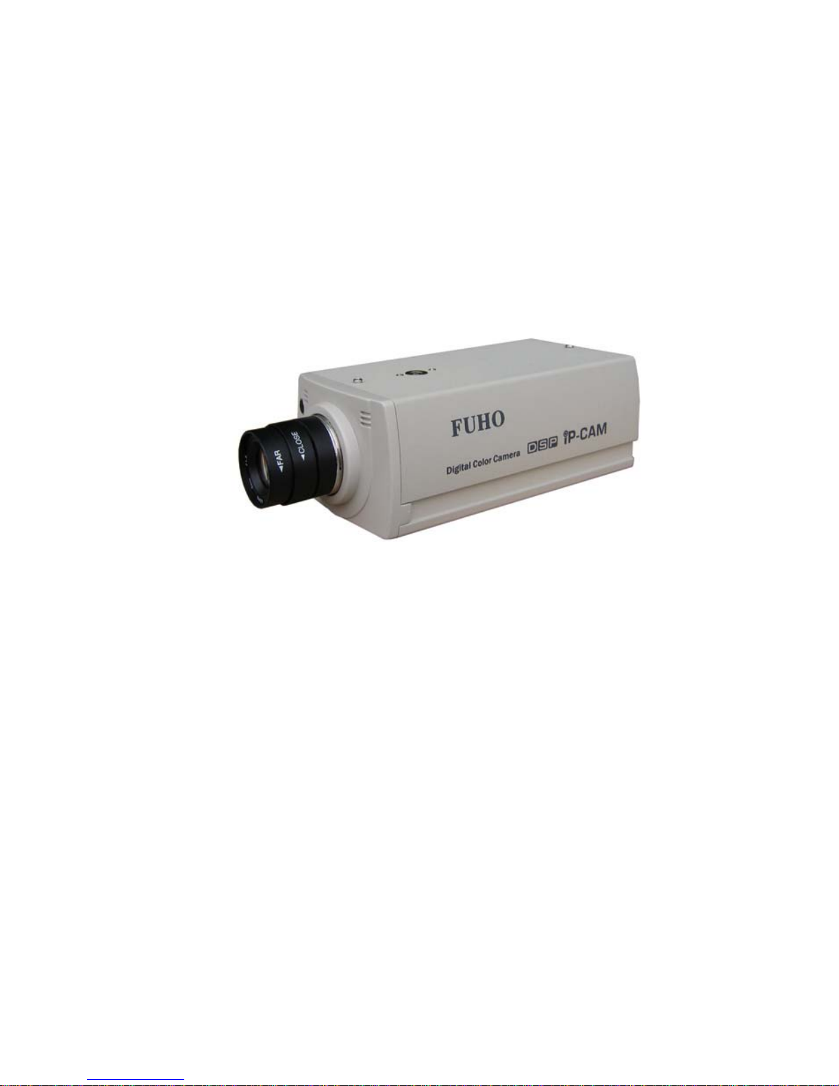
1. OUTLINE
IP-CAM is a low cost provision of network surveillance facility which transmits images on
network to remote PC in format of compression technology. Monitoring, storage and recognition
on line are provided by IP-CAM. Image transmission remains the same quality on both ends of
server site and remote site. Single image source can be transmitted to multi ports saving lots of
cabling overhead.
1.1 INTRODUCTION
Dual compression technology JPEG & MPEG-4, remote site operator can access to the server
site via IE browser to secure personal safeguard and property. IP-CAM works with existing
digital network transmission system. LivePlayer software provides functions of live monitoring,
monitoring setup conditions & motion/schedule recording.

IP901 User’s Manual
Page 5
1.2 FEATURE
;Image & audio transmission via network
;Dynamic IP & static IP support
;Dual compression technology JPEG & MPEG-4
;Digital alarm I/O
;RS-485 for PTZ control
;LivePlayer client software
;Built in motion detection & recording functions
;IE browser remote monitoring & setup support
;Firmware upgrade via IE browser on line
1.3 ACCESSORY
[1] . IP-CAM
[2] . CD ROM
Remarks
[1] . Please contact local dealer in case of accessory shortage
[2] . IP-CAM may be damaged & warranty void in use of other power adaptors
1.4 SYSTEM REQUIREMENT
;Pentium4 or above
;Windows 2000/XP OS
;Protocol comply to 802.11 or ADSL network
;Microsoft Internet Explorer 6.0 or above
;Microsoft Codec Installation Package for Windows Media Player 6.4 or above
( http://www.microsoft.com/windows/windowsmedia/format/codecdownload.aspx )

IP901 User’s Manual
Page 6
1.5 PANELS
1.5.1 FRONT PANEL
Microphone
Build-in Microphone
1.5.2 REAR PANEL
DC +12V
Power input port receives 12VDC power
Video Out
Video output port provides images to monitor or recording devices
RS-485
RS-485 control port for PTZ control
LAN
RJ-45 10/100 Based-T Ethernet transmission port
Reset Button
Press this button to restart

IP901 User’s Manual
Page 7
ALARM I/O
Alarm input/output port two sets for digital sensor input one set for digital alarm output
Definition of the pins
1. +12VDC
2. digital sensor input #1; Hi active
3. digital sensor # 2; Hi active
4. GND。
5. digital output out
6. digital output in
caution: pin #2 & pin #3 are individual input ports Hi active input voltage rated 12VDC
pin #5 & pin #6 are the same output port normal open alarm close
POWER LED
Power indicator power on indicator red
LAN LED
Network indicator LED ON LAN working

IP901 User’s Manual
Page 8
2. INSTALLATION
2.1 CABLING
1. Power Input
Plug in the power adaptor which supplies +12VDC. IP-CAM could be damaged of
improper voltage input. Power LED turns to red in five seconds IP-CAM system
activated.
2. Plug in Ethernet Cable
Plug the cable in the Ethernet port with “LAN" mark for Ethernet connection.
Ethernet port
Power Input

IP901 User’s Manual
Page 9
3. Video Output
“VIDEO OUTPUT" is to be connected to CCTV monitor for live monitoring. The
video output format is 1 Vp-p Composite Video Signal, 75 Ω
4. RS-485 Connection
RS-485 --- Pan Tilt Control Port. User can setup pan tilt control on IE browser.
Please keep alert on the polarity D+ & D- of RS-485 port.
RS-485
Video Output

IP901 User’s Manual
Page 10
2.2 SURVEILLANCE SOFTWARE
Please use the enclosed CD ROM to install the software
1. Put the CD ROM in CD drive
2. Execute the file “Liveplayer_Setup.exe” to start installation. This software promptly
supports OS of English, traditional Chinese & simplified Chinese.
3. Click “Next” to initiate software
installation
4. Click “Next” in the dialog of
“Choose Components”
5. Choose the default directory
Indice
Altri manuali Fuho Telecamera IP


