GammaSwiss RoofMate Manuale del proprietario

ROOF & GUTTER
DEICING
YEAR
LIMITED
WARRANTY
30
YEARS
OF EXPERTISE
IN ELECTRIC
CABLE HEATING
Installation and Operation
Instructions

2
CONTENTS
ALWAYS/NEVER...................................................................................................................... 4
1 SAFETY MEASURES .......................................................................................................... 5
2 PRE-INSTALLATION CHECKLIST............................................................................. 6
2.1 Purpose of the Product............................................................................................... 6
2.2 Heating Cable Specifications ................................................................................... 7
2.3 Consumed Power ......................................................................................................... 8
2.4 Installers.......................................................................................................................... 9
2.5 When to Install RoofMate........................................................................................ 9
2.6 Where to Install RoofMate ...................................................................................... 9
2.7. Determining Necessary Cable Length................................................................. 9
3 ROOF REQUIREMENTS................................................................................................ 12
4 ELECTRICAL SYSTEM REQUIREMENTS............................................................... 12
5 HEATING CABLE INSTALLATION........................................................................... 14
5.1 Location of the Heating Cable................................................................................ 14
5.2 Proper Handling and Maintenance of the Heating Cable .......................... 20
5.3 Testing the Heating Cable ...................................................................................... 20
5.4 Roof, Gutters, and Drainage Pipes Preparation .............................................. 20
5.5 Mounting on Roof...................................................................................................... 20
5.6 Final Steps of Installation....................................................................................... 27
6 HEATING CABLE USE AND TECHNICAL MAINTENANCE ....................... 28
6.1 Pre-Season Inspections ........................................................................................... 28
6.2 Turning the Heating Cable On and Off ............................................................. 29
6.3 Checking the Operation and Condition of the Heating Cable ................ 29
6.4 Actions in Case of Circuit Breaker Trip or a Blown Fuse............................ 30
6.5 Off-Season Use .......................................................................................................... 30
7 REMOVING THE HEATING CABLE ........................................................................ 30
8 WARRANTY LIMITATION AND RESPONSIBILITY ......................................... 31

Installation and Operation Instructions 3
Thank you for purchasing RoofMate —
For roof and gutter de-icing!
Please thoroughly read the manual before installation, operation, and for tech-
nical maintenance of the product. Protect yourself and people around you by
following the safety requirements. Failing to follow the instructions in this
manual may result in personal injury and/or property damage. Retain instruc-
tions for future reference. To ensure warranty service, you must follow the re-
quirements outlined here in the Installation Manual. Installation of the heating
cable must be carried out by persons authorized to carry out electrical work.
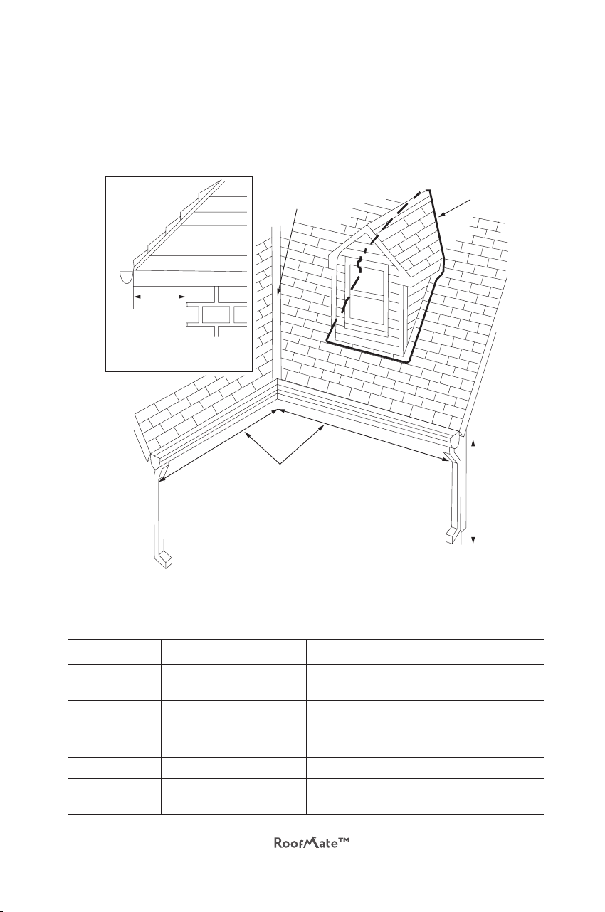
eave
eave
depth
depth
drainage pipe
drainage pipe
drainage pipe
valley
valley
valley
drip
loop
tracing
tracing
width
width
tracing
height
eave
length
tracing
width
eave
depth
General view of the roof and basic terms

4
ALWAYS/NEVER
NEVER:
Install a damaged heating cable
Allow or use sharp objects to damage/modify heating cables
Twist the cables
Use heating cables for purposes other than what’s described in the manual
Place heating cables under roofing material, inside walls or in enclosed
spaces
Connect a heating cable designed for 120 V to a 230 V power source
Exceed the maximum length of electrical circuit as it will lead to power
shutdown during the operation
Install heating cables on surfaces that can become hotter than 150°F (65°C)
Turn-on the cable at very low ambient temperatures, as this can overload
the circuit
Try to cut, shorten, or modify a heating cable as it can cause an electric
shock or fire
ALWAYS:
Turn the heating cable OFF at ambient temperatures above 50°F (10°C)
Before installing the heating cable, make sure the installation location is
cleaned of leaves, branches and other debris
Check the system every season before switching on
Ensure a bend radius of the heating cable of at least 1-inch during installa-
tion and operation
Make sure that the heating cable is installed by a qualified technician in
accordance with this installation manual and a NATIONAL ELECTRICAL
CODE (NEC). All electrical connections must be made by a qualified elec-
trician in accordance with all electrical and building codes in your area

Installation and Operation Instructions 5
1. SAFETY MEASURES
WARNING
Improper installation, use, operation or maintenance of this product may result
in personal injury or death from electric shock or fire, as well as property dam-
age. Read and follow the instructions in this manual carefully.
1.1 To reduce the risk of injury/death from electric shock or fire, strictly comply
with all electrical and construction requirements for the use of this product
(for more information, see the “Electrical System Requirements” section). It is
mandatory to use an external 120 V AC outlet that meets all the following re-
quirements:
It is electrically grounded
Ground fault protection is provided through the use of a ground fault
circuit interrupter (GFCI). Maximum leak current 30 mA
It is used with appropriate rated current
It’s protected from the weather
It’s located within 6-feet of the starting point of the heating cable on the
roof
If you are not sure if your electrical outlet meets these requirements, contact
a licensed electrician.
1.2 The installation of the heating cable must be in accordance with the Nation-
al Electrical Code (NEC).
1.3 Make sure that all power supplies are turned off before installing or servicing
a cable.
1.4 Do not twist the cable during installation.
1.5 When using on a roof, do not install the cable under roofing materials.
1.6 Do not expose the cable to temperatures above 150°F, as this may damage
the cable.
1.7 Do not use extension cords.
1.8 For warranty service, make sure that the heating cable is installed in accor-
dance with the requirements of this manual.
1.9 Do not cut or attempt to change the length of the heating cable, as this may
result in a short circuit and electric shock.

6
2. PRE-INSTALLATION CHECKLIST
2.1 Purpose of the Product
The heating cable is designed to prevent the formation of ice deposits on roofs.
Do not install heating cables to remove already-formed ice deposits or to clear
the roof of ice and snow. Do not use heating cables for any other purpose, for
example, to melt snow on sidewalks or to protect pipes from freezing. We offer
other products designed for these purposes. Consult a professional roofer for
expert advice.
1.10 Do not install the heating cable where it may be subjected to additional
heating, for example, near ventilation, exhaust openings or a chimney.
1.11 Do not paint the cable or expose it to chemicals such as adhesives or
sealants.
1.12 Keep all combustible materials, such as leaves and branches, away from the
heating cable. Do not install heating cables on wooden parts of the structure
(cannot be used on wooden shingles).
1.14 Do not use a damaged or corrupt heating cable.
Signs of damage include cuts, brittleness, carbonization, cracking, surface dis-
coloration, and bare wires.

Installation and Operation Instructions 7
Copper
conductors
Self-regulating
heating matrix
Inner
insulation
Protective
braid
Outer jacket
Figure 1. Heating cable description
Table 1. Heating Cable Specifications
Type of heating cable Self-regulating
Rated voltage, V 110–120 V
Power output at 50°F 7 W/ft
Power output at 32°F 10 W/ft
Length of heating cable 6–150 ft
Dimensions of heating cable 13.0×6.0 mm
Bus wires 16 gauge AWG
Minimum bending radius 1 inch
Outer jacket material Thermoplastic elastomer
Braid material Tinned copper
Maximum working temperature 185°F
Power cord Weatherproof, 10 ft, 3-conductor 14 AWG, with
LED-plug
2.2 Heating Cable Specifications

8
2.3 Consumed Power
Table 2 below shows the power consumed by the pre-assembled self-regulat-
ing RoofMate heating cable.
Table 2. Consumed Power
Length
,
ft.
Power output
(watts) at
Temperature RoofMate Model
50°F
(10°С)
32°F
(0°С)
6 42 67
Parallel Pre-assembled self-regulating heating cable 7-RM1-006-10
12 84 134
Parallel Pre-assembled self-regulating heating cable 7-RM1-012-10
18 126 201
Parallel Pre-assembled self-regulating heating cable 7-RM1-018-10
24 168 269
Parallel Pre-assembled self-regulating heating cable 7-RM1-024-10
37 259 410
Parallel Pre-assembled self-regulating heating cable 7-RM1-037-10
50 350 560
Parallel Pre-assembled self-regulating heating cable 7-RM1-050-10
62 435 700
Parallel Pre-assembled self-regulating heating cable 7-RM1-062-10
75 525 840
Parallel Pre-assembled self-regulating heating cable 7-RM1-075-10
87 610 980
Parallel Pre-assembled self-regulating heating cable 7-RM1-087-10
100 701 1120
Parallel Pre-assembled self-regulating heating cable 7-RM1-100-10
112 785 1250
Parallel Pre-assembled self-regulating heating cable 7-RM1-112-10
125 876 1400
Parallel Pre-assembled self-regulating heating cable 7-RM1-125-10
137 960 1535
Parallel Pre-assembled self-regulating heating cable 7-RM1-137-10
150 1050 1680
Parallel Pre-assembled self-regulating heating cable 7-RM1-150-10

Installation and Operation Instructions 9
2.4 Installers
Installation of the heating cable must be carried out by persons authorized to
carry out electrical work.
2.5 When to Install RoofMate
The heating cable should be installed when there is no ice or snow on the roof.
Do not use the heating cable to melt the snow and ice that has already formed
on your roof. If snow and ice are already on the roof, consult a professional
roofer for help. Heating cables should only be installed after the ice and snow
have melted and/or are removed. The temperature when installing the cable
should be between 32 and 80°F (0 to 27°C).
2.6 Where to Install RoofMate
The heating cable should be installed on areas of the roof where ice deposits,
including icicles, can form. Depending on the influence of the sun, the prevail-
ing wind direction and the shape of the roof, cables can be installed both over
the entire roof area, and in individual sections.
2.7. Determining Necessary Cable Length
An accurate estimate of the cable length required is very important as it is not
possible to alter or modify a cables length. The cable should be installed on
the areas of the roof where ice forms. This can be the entire edge of the roof or
in individual sections. The cable must also be installed in any nearby gutters,
drainage pipes and/or valleys.
If you need to install a cable on a roof with gutters, drainage pipes, valleys and/
or attic windows, follow the instructions “A. For Typical Applications.”
If you need to install the cable only in the gutters and drainage pipes, follow the
instructions “B. For Installation in a Gutter and Drain Only.”
Use Figure 2 for Tables 3, 4, and 5.

10
A. For Typical Applications
Step 1. For each area shown in Figure 2, measure the required dimensions and
then calculate the necessary cable length (see Figure 2, Tables 3 and 4).
Add the results to determine the total length of the cable.
Figure 2.
E
B
CD
A
Table 3. Cable Length Calculation
Location What to Measure How to Calculate
Along the roof Eave depth (A)
Eave (Roof) length (B) Eave length(B) x Multiplier (see Table. 4)
Attic window The perimeter around
the attic windows (C) Number of attic windows × perimeter (C)
Valley Number of valleys (D) Number of valleys × 6-feet
Gutter Gutter length (B) Gutter Length × 2
Drainage pipe Drainage pipe length (E) Number of drainage pipes × length of
drainage pipes × 2
Questo manuale è adatto per i seguenti modelli
1
Indice