GE 25983 Manuale utente

Model 25983
5.8GHz Dual Handset
Speakerphone/Answering
System
User’s Guide

Important Information
NOTICE: This product meets the applicable Industry Canada technical specications.
Operation is subject to the following two conditions: (1) This device may not cause interference, and () This
device must accept any interference, including interference that may cause undesired operation of the
device.
The equipment must be installed using an acceptable method of connection. The customer should
be aware that compliance with the above conditions may not prevent degradation of service in some
situations.
Repairs to certied equipment should be made by an authorized Canadian maintenance facility designated
by the supplier. Any repairs or alterations made by the user to this equipment, or equipment malfunctions,
may give the telecommunications company cause to request the user to disconnect the equipment.
Users should ensure for their own protection that the electrical ground connections of the power
utility, telephone lines and internal metallic water pipe systems, if present, are connected together. This
precaution may be particularly important in rural areas.
CAUTION: Users should not attempt to make such connections themselves, but should contact the
appropriate electric inspection authority, or electrician, as appropriate.
NOTES: This equipment may not be used on coin service provided by the telephone company.
Interference Information
This equipment generates and uses radio frequency energy which may interfere with residential radio and
television reception if not properly installed and used in accordance with instructions contained in this
manual. Reasonable protection against such interference is ensured, although there is no guarantee this
will not occur in a given installation. If interference is suspected and veried by switching this equipment on
and off, the user is encouraged to try to correct the interference by one or more of the following measures:
Reorient the radio/television receiver’s antenna, relocate the equipment with respect to the receiver, plug
the equipment and receiver into separate circuit outlets. The user may also wish to consult a qualied
radio/television technician for additional suggestions. This equipment has been fully tested and complies
with all limits for Class B computing devices pursuant to part 15 FCC Rules and Regulations.

Telephone Network Information
Should your equipment cause trouble on your line which may harm the telephone network, the telephone
company, where practicable, may notify you that temporary discontinuance of service may be required.
Where prior notice is not practicable and the circumstances warrant such action, the telephone company
may temporarily discontinue service immediately.
The telephone company may make changes in its communications facilities, equipment, operations or
procedures where such action is required in the operation of its business. If these changes are expected
to affect the use or performance of your telephone equipment, the telephone company will likely give you
adequate notice to allow you to maintain uninterrupted service.
Notice must be given to the telephone company upon termination of your telephone from your line.
REN Number
On the bottom of this equipment is a label indicating, among other information, the Ringer Equivalence
Number (REN) for the equipment.
The REN is useful in determining the number of devices you may connect to your telephone line and still
have all of these devices ring when your telephone number is called. In most (but not all) areas, the sum of
the RENs of all devices connected to one line should not exceed 5. To be certain of the number of devices
you may connect to your line as determined by the REN, you should contact your local telephone company.
REN Number is located on the cabinet bottom.
Licensing
Licensed under US Patent 6,47,009.
Hearing Aid Compatibility (HAC)
This telephone system meets FCC/Industry Canada standards for Hearing Aid Compatibility.
FCC RF Radiation Exposure Statement
This equipment complies with FCC RF radiation exposure limits set forth for an uncontrolled environment.
This equipment should be installed and operated with a minimum distance of 0 centimeters between the
radiator and your body. This transmitter must not be co-located or operated in conjunction with any other
antenna or transmitter.

4
Table of Contents
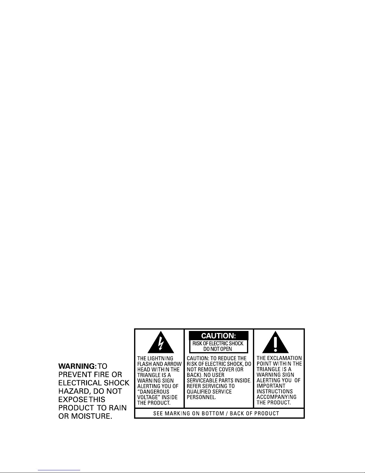
Important InformatIon .................................2
Interference InformatIon .............................2
telephone network InformatIon .................3
ren number ...............................................3
lIcensIng .....................................................3
hearIng aId compatIbIlIty (hac) .................3
fcc rf radIatIon exposure statement ........3
IntroductIon ...............................................6
before you begIn ........................................6
Parts CheCklist ...........................................6
telePhone JaCk requirements.........................6
InstallatIon .................................................7
Digital seCurity system ...................................7
imPortant installation guiDelines .................7
handset and charge cradle layout ............8
base layout .................................................8
InstallIng the phone ....................................9
installing the hanDset Battery ......................9
installing the Phone .....................................10
ConneCting the aC (eleCtriCal) Power 10
ConneCting the telePhone line ..............10
attaChing the PeDestal BraCket ............11
ConneCting the CorDeD hanDset ..........11
answerIng system set up ..........................11
VoiCe instruCtions .........................................11
answerIng system operatIon ....................12
reCorDing the outgoing announCement ..12
reViewing announCement.............................12
leaVing a message .........................................12
sCreening Calls from the Base ...................13
sCreening Calls from the hanDset ............13
message PlayBaCk from Base unit .............13
erasing messages ..........................................14
leaVing a memo ..............................................14
telephone set up ......................................15
language .........................................................15
hanDset name ................................................16
DisPlay Contrast ...........................................16
rings to answer ............................................16
seCurity CoDe .................................................17
Base ringer leVel ..........................................17
hanDset ringer on/off ............................18
ringer tone ....................................................18
ViP ring tone ................................................18
setting Day/time............................................19
loCal area CoDe ............................................19
tone/Pulse Dialing .......................................20
transfer on/off.........................................20
registration (link CorDless hanDset) .......20
Default setting ..............................................21
basIc operatIon .........................................21
answering a Call ..........................................21
CorDless hanDset ....................................21
CorDeD hanDset .......................................21
Base sPeakerPhone ...................................21
making a Call.................................................22
CorDless hanDset ....................................22
CorDeD hanDset .......................................22
sPeakerPhone .............................................22
manual Channel seleCtion ..........................22
Call timer .......................................................22
auto stanDBy ..................................................22
hanDset ringer on/off shortCut .........23
Do not DisturB .............................................23
flash ................................................................23
Call transfer .................................................24
transferring Call from Base to CorDless
hanDset ......................................................24
transferring Call from CorDless hanDset
to another CorDless hanDset/Base .....24
last numBer reDial .......................................24
Base sPeakerPhone ...................................24
CorDeD hanDset .......................................25
CorDless hanDset ....................................25
holD .................................................................25
Paging the CorDless hanDset .....................25
mute .................................................................26
Volume .............................................................26
sPeakerPhone .............................................26
CorDeD hanDset .......................................26
CorDless hanDset ....................................26
answering system .....................................26

5
Vmwi inDiCator on hanDset .................26
Base unit sPeakerPhone oPeration ............27
reCeiVing a Call with sPeakerPhone .....27
making a Call with sPeakerPhone ........27
switChing Between sPeakerPhone anD
hanDset ......................................................28
ConferenCe the external Caller with
CorDless hanDset anD Base ........................28
memory .....................................................28
storing a name anD numBer in memory ...28
storing a reDial numBer..............................29
inserting a Pause in the Dialing
sequenCe ..........................................................29
reViewing, Changing or Deleting storeD .....
names/numBers .............................................30
Dialing a storeD numBer .............................30
Chain Dialing from memory ........................31
caller Id (cId) .........................................32
Call waiting Caller iD ................................32
reCeiVing CiD reCorDs .................................32
storing CiD reCorDs (in CiD memory) .....33
reViewing Call reCorDs ...............................33
storing CiD reCorDs in internal
memory ............................................................34
Dialing a Caller iD numBer ........................34
Deleting the Current Caller iD reCorD ...35
Deleting all Caller iD reCorDs.................35
Caller iD errors ...........................................36
remote access ...........................................36
using the hanDset.........................................36
answering system inDiCator ........................36
memory full ...................................................36
aCCessing the answering system from
another loCation ..........................................37
Changing the seCurity CoDe .......................37
changIng the battery ................................38
Battery safety PreCautions .........................38
dIsplay messages .......................................39
handset sound sIgnals .............................40
troubleshootIng guIde ..............................41
telePhone solutions ................................41
Caller iD solutions .................................42
Battery solutions .....................................42
causes of poor receptIon ..........................43
general product care ..............................43
warranty ..................................................44
accessory InformatIon ..............................45
Index .........................................................46

6
For Model 25983xx3 there will be ONE additional handset, charge cradle, battery
pack and cover than shown above.
Telephone Jack Requirements
To use this phone, you need an RJ11C type modular telephone
jack, which might look like the one pictured here, installed in your
home. If you don’t have a modular jack, call your local phone
company to nd out how to get one installed.
Introduction
CAUTION: When using telephone equipment, there are basic
safety instructions that should always be followed. Refer to the
IMPORTANT SAFETY INSTRUCTIONS provided with this product
and save them for future reference.
Before You Begin
Parts Checklist (for 598xx model)
Make sure your package includes the items shown here.
Modular
telephone
line jack
Wall plate
Base
Handset
Desk pedestal/Wall
mount bracket
AC power
adaptor
Telephone line cord
Handset battery pack
Coiled handset
cord
Base Handset
Charge cradle
Battery
compartment door

7
Installation
Digital Security System
Your cordless phone uses a digital security system to protect against false ringing,
unauthorized access, and charges to your phone line.
INSTALLATION NOTE: Some cordless telephones operate at
frequencies that may cause or receive interference with nearby
TVs, microwave ovens, and VCRs. To minimize or prevent such
interference, the base of the cordless telephone should not be
placed near or on top of a TV, microwave ovens, or VCR. If such
interference continues, move the cordless telephone farther away
from these appliances.
Certain other communications devices may also use the 5.8 GHz
frequency for communication, and, if not properly set, these
devices may interfere with each other and/or your new telephone.
If you are concerned with interference, please refer to the owner’s
manual for these devices on how to properly set channels to avoid
interference. Typical devices that may use the 5.8 GHz frequency
for communication include wireless audio/video senders, wireless
computer networks, multi-handset cordless telephone systems,
and some long-range cordless telephone systems.
Important Installation Guidelines
• Avoid sources of noise and heat, such as motors, uorescent lighting, microwave
ovens, heating appliances and direct sunlight.
• Avoid areas of excessive dust, moisture and low temperature.
• Avoid other cordless telephones or personal computers.
• Never install telephone wiring during a lightning storm.
• Never install telephone jacks in wet locations unless the jack is specically
designed for wet locations.
• Never touch non-insulated telephone wires or terminals, unless the telephone line
has been disconnected at the network interface.
• Use caution when installing or modifying telephone lines.

8
Handset and Charge Cradle Layout
charge cradle with
power adaptor
charge indicator
Base Layout
format/trans
(format/ transfer
button) delete (button)
erase (button)
redial (button)
TALK/CALL BACK
(button)
*TONE/exit (button)
mute/menu (button) ash/call waiting/
answerer (button)
display
play/stop (button) skip (button)
#PAUSE/ringer
(button)
repeat (button)
mem
(memory button)
CALLER ID-VOLUME
6(button)
CALLER ID-VOLUME
5(button)
visual ringer
chan
(channel button)
microphone
display
memo
(button)
mailbox 1/2/3
play/stop (buttons)
caller id :
(: button)
memory
(button)
redial (button)
page/transfer
(button)
speaker/call back
(button)
hold (button)
speaker volume
+/- (button)
hs volume
(handset volume
button)
delete
(button)
ans on/off
(answerer on/off
button)
format (button)
*exit (button) microphone
mute/do not disturb
(button)
#pause
(button)
menu/ash (button)
announce
(button)
caller id 9
(9 button)
SL

9
Installing the Phone
Installing the Handset Battery
NOTE: You must connect the handset battery before using the
cordless handsets.
CAUTION: To reduce the risk of re or personal injury, use only
the Thomson Inc. approved Nickel-Cadmium (Ni-Cd) battery
model 5-2729 or Nickel-Metal Hydride (Ni-MH) battery model
5-2522, which is compatible with this unit.
1. Locate battery and battery door which are packaged together inside a plastic bag
and are separate from the handset.
. Locate the battery compartment on the back of the handset.
. Plug the battery pack cord into the jack inside the compartment.
NOTE: It is important to maintain the polarity (black and red wires)
to the jack inside the compartment. To ensure proper battery
installation, the connector is keyed and can be inserted only one way.
4. Insert the battery pack.
5. Close the battery compartment by pushing the door up until it snaps into place.
6. Place the handsets in the charging cradles. Allow handsets to charge for 16 hours
prior to rst use. If you don’t properly charge the handsets, battery performance is
compromised.
black wire
red wire
battery
pack
PRESS DOWN
FIRMLY

10
Installing the Phone
Choose the best location to install your base and handset charge cradles. Your base
and handset charge cradles should be placed on a level surface such as a desk or
table top, or you may mount the base on a wall.
Connecting the AC (Electrical) Power
1. On the base, plug the power adaptor cord into the power jack on the back of the
base and the other into an electrical outlet.
CAUTION: To reduce risk of personal injury, re, or damage
use only the 5-2760 power adaptor listed in the user’s guide.
This power adaptor is intended to be correctly orientated in a
vertical or oor mount position.
. Plug the handset charge cradle into an electrical outlet.
NOTE: The charge indicator on the handset charge cradle turns on
to indicate the handset battery is charging
Connecting the Telephone Line
On the base, plug one end of the straight telephone line cord into the jack on the back
of the base and the other end into a modular wall telephone jack.
NOTE: If desired, gather the extra telephone line and power
adaptor cord together and store inside the pedestal bracket.
Indice
Lingue:
Altri manuali GE Telefono


