GE 29879 Manuale utente

29879
We bring good things to life.
Trimline Phone with Digital
Answering System
User's uide

2
FCC REGISTRATION INFORMATION
Your telephone equipment is registered with the Federal Communications Commission and is in compliance with
parts 15 and 68, FCC Rules and Regulations.
1Notification to the Local Telephone Company
On the bottom o this equipment is a label indicating, among other in ormation, the FCC Registration number
and Ringer Equivalence Number (REN) or the equipment. You must, upon request, provide this in ormation to
your telephone company.
The REN is use ul in determining the number o devices you may connect to your telephone line and still have
all o these devices ring when your telephone number is called. In most (but not all) areas, the sum o the
RENs o all devices connected to one line should not exceed 5. To be certain o the number o devices you may
connect to your line as determined by the REN, you should contact your local telephone company.
Notes
• This equipment may not be used on coin service provided by the telephone company.
• Party lines are subject to state tari s, and there ore, you may not be able to use your own telephone
equipment i you are on a party line. Check with your local telephone company.
• Notice must be given to the telephone company upon permanent disconnection o your telephone rom
your line.
2Rights of the Telephone Company
Should your equipment cause trouble on your line which may harm the telephone network, the telephone
company shall, where practicable, noti y you that temporary discontinuance o service may be required.
Where prior notice is not practicable and the circumstances warrant such action, the telephone company may
temporarily discontinue service immediately. In case o such temporary discontinuance, the telephone
company must: (1) promptly noti y you o such temporary discontinuance; (2) a ord you the opportunity to
correct the situation; and (3) in orm you o your right to bring a complaint to the Commission pur suant to
procedures set orth in Subpart E o Part 68, FCC Rules and Regulations.
The telephone company may make changes in its communications acilities, equipment, operations o
procedures where such action is required in the operation o its business and not inconsistent with FCC Rules
and Regulations. I these changes are expected to a ect the use or per ormance o your telephone equipment,
the telephone company must give you adequate notice, in writing, to allow you to maintain uninterrupted service.
INTERFERENCE INFORMATION
This device complies with Part 15 o the FCC Rules. Operation is subject to the ollowing two conditions: (1) This
device may not cause harm ul inter erence; and (2) This device must accept any inter erence received, including
inter erence that may cause undesired operation.
This equipment has been tested and ound to comply with the limits or a Class B digital device, pur suant to Part
15 o the FCC Rules. These limits are designed to provide reasonable protection against harm ul inter erence in a
residential installation.
This equipment generates, uses, and can radiate radio requency energy and, i not installed and used in
accordance with the instructions, may cause harm ul inter erence to radio communications. However, there is no
guarantee that inter erence will not occur in a particular installation.
I this equipment does cause harm ul inter erence to radio or television reception, which can be determined by
turning the equipment o and on, the user is encouraged to try to correct the inter erence by one or more o the
ollowing measures:
• Reorient or relocate the receiving antenna (that is, the antenna or radio or television that is “receiving” the
inter erence).
• Reorient or relocate and increase the separation between the telecommunications equipment and recei ving
antenna.
• Connect the telecommunications equipment into an outlet on a circuit di erent rom that to which the
receiving antenna is connected.
I these measures do not eliminate the inter erence, please consult your dealer or an experienced radio/
television technician or additional suggestions. Also, the Federal Communications Commission has
prepared a help ul booklet, “How To Identi y and Resolve Radio/TV Inter erence Problems.” This booklet is
available rom the U.S. Government Printing O ice, Washington, D.C. 20402. Please speci y stock number
004-000-00345-4 when ordering copies.
FCC NUMBER IS LOCATED ON THE CABINET BOTTOM
REN NUMBER IS LOCATED ON THE CABINET BOTTOM

3
TABLE OF CONTENTS
PLAYIN MESSA ES ........................... 21
ERASING ALL MESSAGES .............. 23
LEAVING A MEMO ....................... 23
2-WAY RECORD .......................... 24
SCREENING CALLS (AUTO
DISCONNECT FEATURE) ............. 24
REMOTE ACCESS ................................ 25
TO ACCESS YOUR ANSWERING
SYSTEM .................................. 25
TELEPHONE BASICS ............................. 26
SETTING T HE RINGER VOLUME ....... 26
SETTING T HE HANDSET VOLUME .... 26
TONE/PULSE DIALING .................. 26
TEMPORARY T ONE DIALING ........... 27
FLASH ....................................... 28
REDIAL ...................................... 28
TROUBLESHOOTIN T IPS ....................... 29
ENERAL PRODUCT CARE .................... 33
SERVICE ............................................ 33
INDEX ............................................... 34
LIMITED WARRANTY ............................ 36
REMOTE ACCESS CARD ........................ 37
FCC REGISTRATION INFORMATION .... 2
INTERFERENCE INFORMATION ............ 2
INTRODUCTION ..................................... 4
BEFORE Y OU BE IN .............................. 4
PARTS CHECKLIST ............................. 4
MODULAR JACK REQUIREMENTS .......... 5
INSTALLING THE BATTERY ................ 5
INSTALLATION ....................................... 6
DESKTOP INSTALLATION ...................... 6
WALL MOUNT INSTALLATION .................. 8
IMPORTANT INSTRUCTIONS FOR
MOVING THE UNIT: ........................ 10
SETUP ...............................................11
RECORDING THE GREETING ............. 11
CHAN IN THE SETTIN S ..................... 13
SETTING THE T IME/DAY ................. 13
DAY .......................................... 13
HOUR ........................................ 14
MINUTES ................................... 14
SETTING THE RINGS TO ANSWER .... 16
TOLL SAVER ............................... 16
INCOMING MESSAGE LENGTH ........ 16
SETTIN THE SECURITY CODE ............... 17
ANSWERERIN SYSTEM OPERATION ....... 19
ADJUSTING THE VOLUME ............... 19
ANSWER ON/OFF INDICATOR ......... 19
MESSAGES INDICATOR .................. 20
4
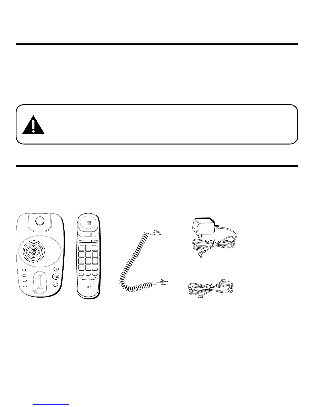
Base Coiled handset
cord
Telephone line cord
INTRODUCTION
Your Digital Answering System is designed to give you lexibility in use
and high quality per ormance. To get the most rom your new Answering
System, we suggest that you take a ew minutes right now to read through
this instruction manual.
CAUTION: When using telephone equipment, there are basic safety
instructions that should always be followed. Refer to the IMPORTANT
SAFETY INSTRUCTIONS provided with this product and save them for
future reference.
BEFORE YOU BEGIN
PARTS CHECKLIST
Make sure your package includes the ollowing items:
TIME SET/STOP
ANSWERER ON/OFF
GREETING
MEMO
ERASE
PLAY
NEXT
PREVIOUS
FLASH
STORE REDIAL
MEM DIAL
BC
A
WXYZ
9
#
TONE
*
TUV
8
PQRS
7
MNO
6
JKL
5
HI
4
DEF
3
ABC
2
1
OPER
0
Handset
AC power supply
5
-
-
+
+
Battery clip
Battery
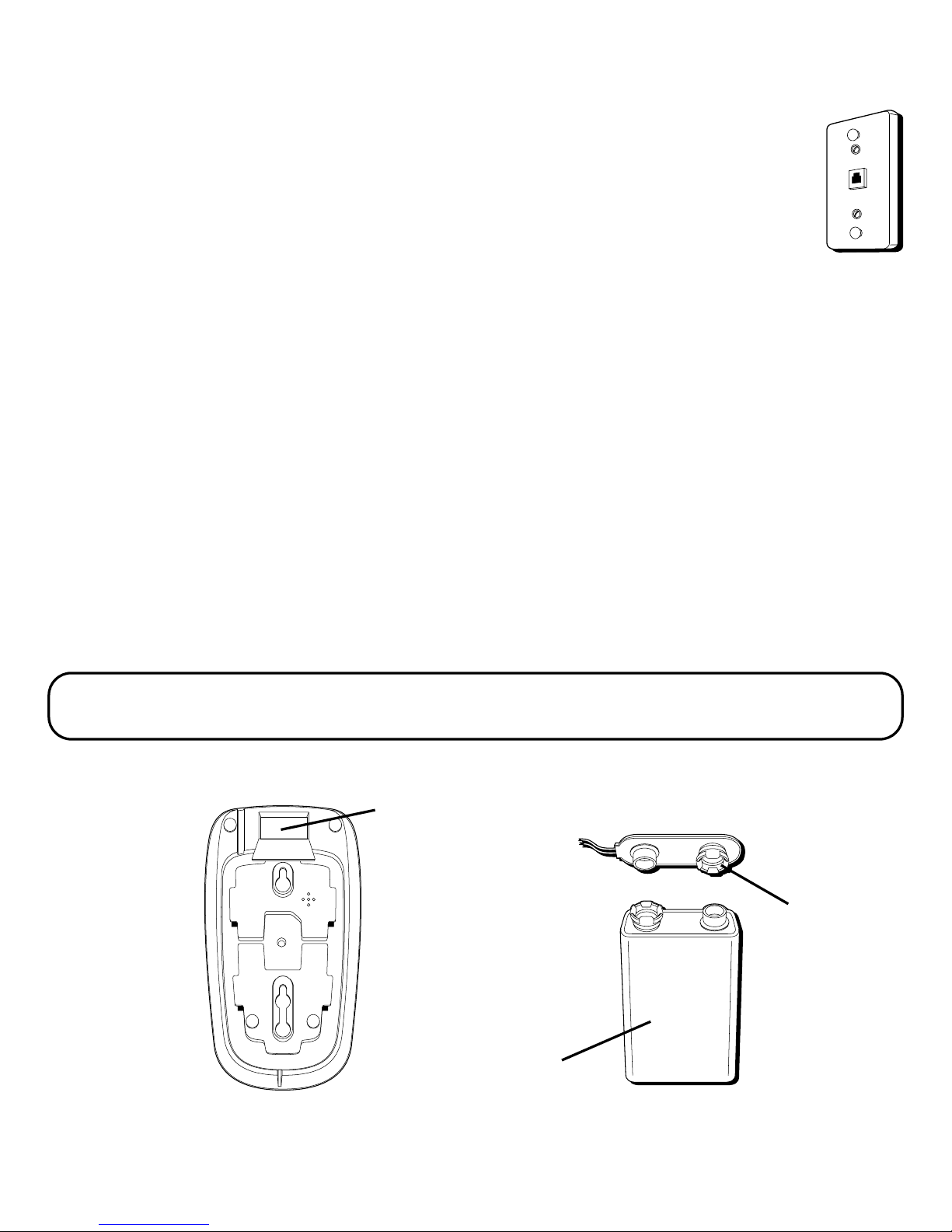
MODULAR JACK REQUIREMENTS
You need an RJ11 type modular jack, which is the most common
type o phone jack and might look like the one pictured here. I
you don’t have a modular jack, call your local phone company to
ind out how to get one installed.
INSTALLING THE BATTERY
In the event o a power loss, a 9-volt alkaline battery (not included) enables
the answering system to retain messages stored in memory. To install the
battery:
1. Remove the battery compartment door on the bottom o the unit by
loosening the screw with a Phillips screwdriver. Li t the door.
2. Connect a resh 9-volt alkaline battery (not included). The large and
small contacts on the battery clip and the battery will interlock. Once
connected, place the battery inside the battery compartment.
3. Replace the battery compartment door and tighten the screw.
NOTE: If the battery is low or not installed, the unit announces “Low Battery” at the end
of your messages.
Battery
compartment

6
INSTALLATION
CAUTION:
• Always disconnect phone cords from the wall outlets before battery
installation or replacement.
• Never install telephone wiring during a lightning storm.
• Never touch uninsulated telephone wires or terminals, unless the
telephone line has been disconnected at the network interface.
• Use caution when installing or modifying telephone lines.
DESKTOP INSTALLATION
1. Plug the coiled cord into the handset. Plug the other end into the jack on
the bottom o the base. Place the handset in the cradle on the base.
2. Plug the line cord into the jack on the bottom o the base. Plug the other
end into a wall jack.
3. Adjust the receiver control switch on the handset to the appropriate
level:
• HI = Highest receiver loudness.
• MID = Receiver loudness is lower.
• NORM = Receiver loudness is lowest.
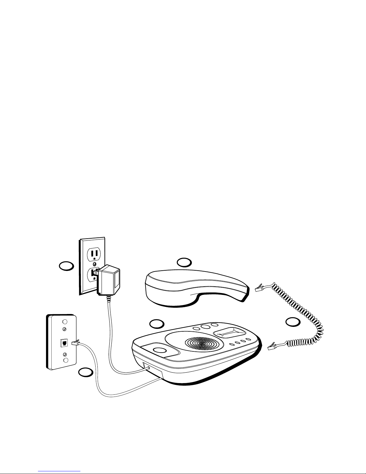
7
4. Plug the two-prong end o the AC power supply into an AC outlet and
the other end into the POWER 9V DC jack on the bottom o the unit. The
unit beeps three times and is ready or setup or to answer calls with the
de ault greeting and settings.
5. Set the RINGER switch on the side o the o the base to the desired
loudness:
• HI = Loudest sound
• LO = Sound will be lower.
• OFF = Telephone will not ring
1
2
3
4
5
8
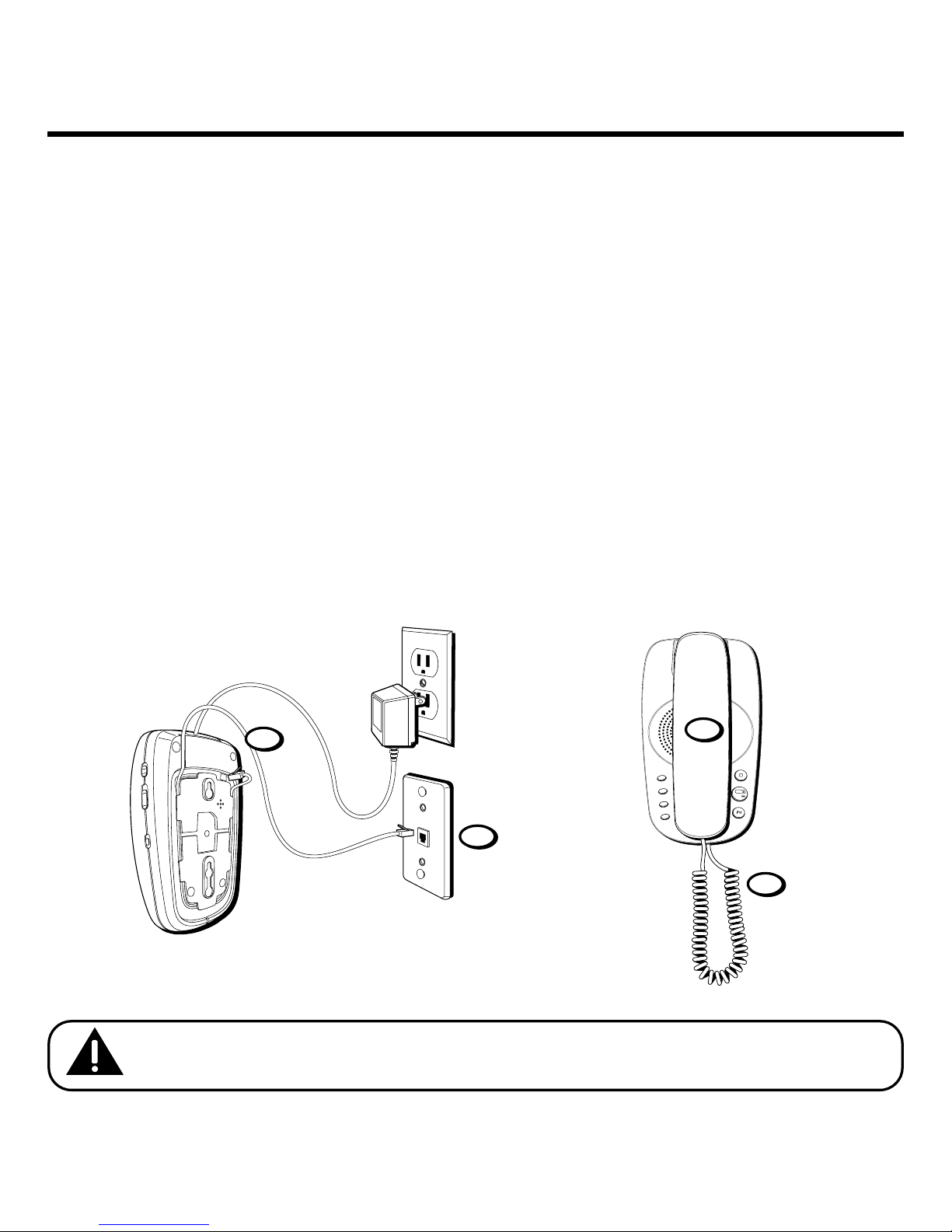
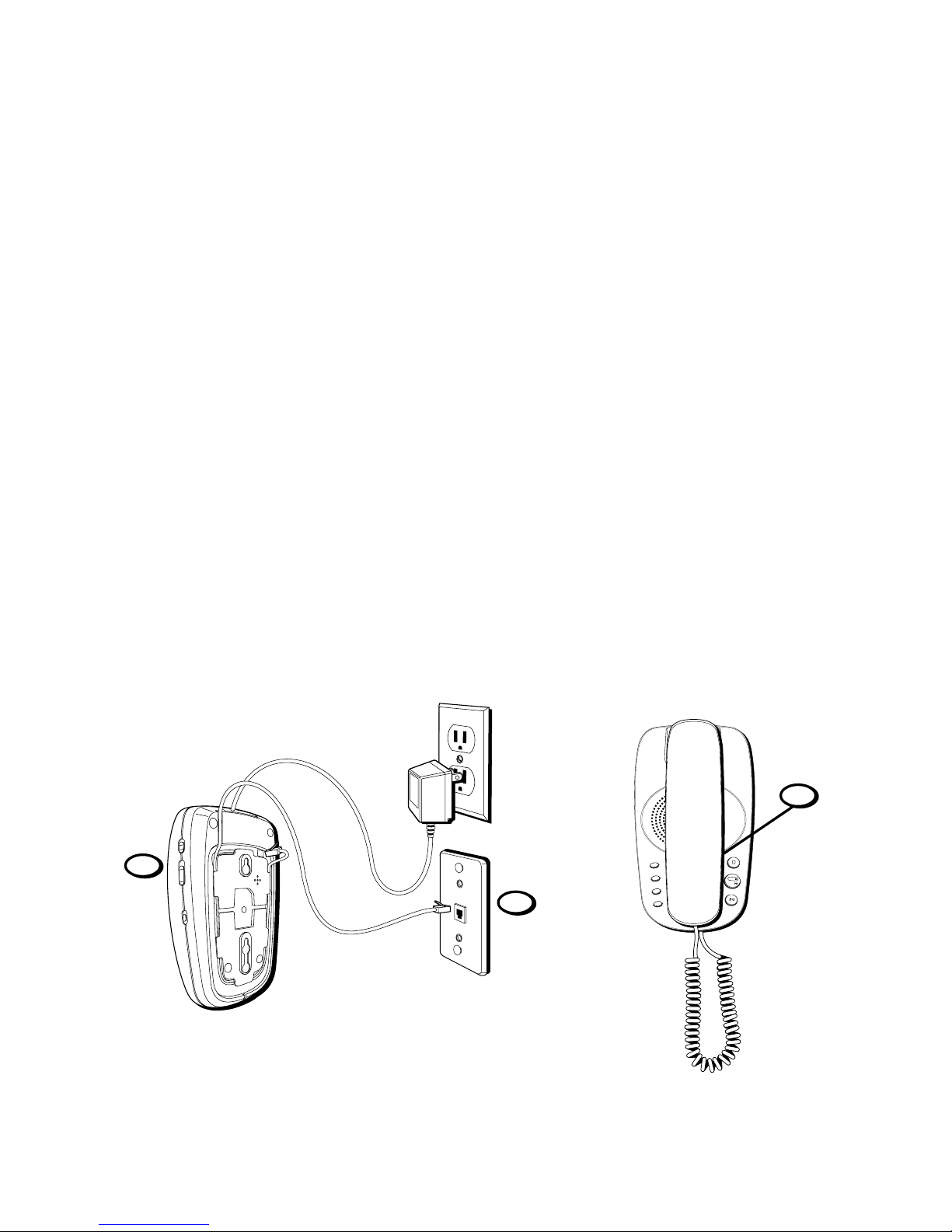
WALL MOUNT INSTALLATION
The phone with digital answering system can be mounted on a wall phone
plate (not included).
1. Plug the phone cord into the phone jack on the bottom o the unit, and
wrap the extra phone line around the bottom o the base. Feed the line
cord through the grooves so that the base area is lat or wall mounting.
2. Connect the other end o the phone line to the modular jack on the wall.
3. Place the handset in the cradle o the base as soon as possible to hang
up the phone.
4. Plug one end o the coiled cord into the handset and the other end into
the jack on the back o the base.
NOTE: Only use the ATLINKS USA, Inc. 5-2498 power supply that was packed
with this unit. Using other power supplies may damage the unit.
TIME SET/STOP
ANSWERER ON/OFF
GREETING
MEMO
ERASE
PLAY
NEXT
PREVIOUS
1
2
3
4
9
5. Slip the mounting holes over the wall plate posts and slide the unit
down irmly into place.
6. Set the TONE/PULSE switch on the side o the handset to TONE or touch-
tone service or PULSE or rotary service.
7. Set the RINGER VOLUME switch as desired.
• HI = Loudest sound
• LO = Sound will be lower.
• OFF = Telephone will not ring
8. The unit is properly installed i you pick up the handset and hear the dial
tone. Otherwise, recheck all installation steps.
5
TIME SET/STOP
ANSWERER ON/OFF
GREETING
MEMO
ERASE
PLAY
NEXT
PREVIOUS
6
7

10
IMPORTANT INSTRUCTIONS FOR MOVING THE UNIT:
To move the answering system to a di erent location in the house, ollow
these instructions:
1. Disconnect the phone line or any phones you may have connected to the
unit.
2. Install a battery, i you have not already done so. This will ensure that
your messages are not lost. See “Installing the Battery.”
3. Go to the electrical outlet and unplug the power supply.
4. Move the unit and phone line to the desired location.
5. Plug in the power supply into an electrical outlet.
6. The MESSAGES indicator blinks when new messages are received.
7. Connect all necessary phone lines.
Altri manuali per 29879
1
Indice
Lingue:
Altri manuali GE Telefono


GE
GE 29115 Series Manuale utente

GE
GE 2-9180 Manuale utente

GE
GE 29484 Manuale utente

GE
GE 25983 Manuale utente

GE
GE Edge 25931EE3 Manuale utente

GE
GE 29267 Manuale utente

GE
GE 28861FE2 - DECT6.0 Corded Phone Manuale utente

GE
GE 27938 Manuale utente

GE
GE 28527 Series Manuale utente

GE
GE BedroomPhone 00023810 Manuale utente


