Getinge 86 SERIES Manuale utente

GETINGE 86-SERIES
INSTALLATION MANUAL
502606400
SEV0725001-

<Doc_INS><Doc_502606400><Rel_A><Lang_GB>
Page 2 of 20
Contents
FOREWORD ____________________________________________3
SAFETY REGULATIONS _________________________________4
General safety regulations ___________________________________ 4
The machine must be assembled and installed: ________________ 4
When the work is complete, check that _______________________ 5
Product liability ____________________________________________ 5
Attention symbols __________________________________________ 5
INSTALLATION__________________________________________6
Wall-mounted model________________________________________ 7
Connecting electric power___________________________________ 8
Alternative connection arrangements _________________________ 9
Connecting water, steam, waste and dryer ____________________ 10
Function check ____________________________________________ 13
TECHNICAL DATA_______________________________________15
Water quality - washer disinfectors_______________________18
Page 3 of 20
<Doc_INS><Doc_502606400><Rel_A><Lang_GB>
FOREWORD
This user manual is intended for users of Getinge 86-series washer disinfectors.
The instruction manual describes the design and operation of the machine and the main-
tenance for which the user is responsible. The purpose of the information in the manual
is to ensure safe operation and optimum efciency.
Before using the machine for the rst time, users must have read this instruction manual
and familiarized themselves with the operation of the machine and its safety instructions.
To conform to EN ISO 15883, the items must be placed in the proper accessories,
recommended by Getinge Disinfection AB.
The customer is responsible for ensuring that an Installation Qualication, an Operating
Qualication and a Performance Qualication according to EN ISO 15883 are carried
out before the product goes into service.
Read the user manual before using the machine.
The information in this manual describes the machine as dispatched from Getinge.
There may be differences due to customization.
The machine is accompanied by the following documentation:
• User manual
• Installation manual (this book)
• Technical manual
• Spare parts list
Getinge reserves the right to change the specication and design without prior notice.
The information in this manual was up to date on the date of issue of the manual.
© Copyright
The content of this manual must not be copied, in
whole or in part, without the written consent of Getinge.

<Doc_INS><Doc_502606400><Rel_A><Lang_GB>
Page 4 of 20
SAFETY REGULATIONS
This machine has been designed with a number of built-in safety devices.
To avoid injury, it is highly important not to bypass or disable these safety devices.
If the equipment is used in a manner that was not specied by the manufacturer, the
safety equipment on the machine may not be fully effective.
Operators and maintenance personnel must undergo safety training for the machine.
All personnel who handle chemicals for washing and disinfection must understand the
washing process, possible health hazards and ways of detecting leaks of toxic chemicals.
Operators and maintenance personnel must undergo regular training in the operation and
maintenance of the equipment. There must be a documented list of personnel who have been
trained on the machine. Trained personal must be tested to verify the training programme.
The equipment must be used in accordance with the safety instructions below.
If in doubt, contact a representative of the reseller without delay.
Important
Take care when handling the chemical agents used in the machine.
Read the instructions on the pack or contact the manufacturer before using the ma-
chine for instructions about:
- what to do if the substance comes into contact with the eyes or skin or if vapors
are inhaled.
- storage of packs and sorting of empty packs for disposal.
The machine must be connected in accordance with the instructions given in the
installation manual.
The machine may only be used by adults.
Installation and servicing may only be done by personnel trained for this machine.
Never bypass door safety switches.
Leaks in the system caused by worn seals in the door, for example, must be re-
paired immediately.
Before doing any repair or servicing work, the personnel concerned must study the
relevant handbooks and service manuals.
Before any welding is done on or close to the machine, all cables connected to the
control system via connectors and sockets must be disconnected.
Before doing any servicing or maintenance work on the machine, isolate it from the
electric power supply and drain all tanks.
Do not wash down or hose down the machine with water.
Take care when using corrosive substances.
Observe safety measures for steam and hot water.
The electrical cabinet may only be opened by authorized and trained personnel.
Spare parts must be obtained only via Getinge EDC.
The machine must be assembled and installed:
by qualied personnel.
in accordance with current local regulations and rules.
Warning:
To avoid the risk of back injury, this equipment should be assembled and
installed by two people.
•
•
•
•
•
•
•
•
•
•
•
•
•
•
•
•
•
Page 5 of 20
<Doc_INS><Doc_502606400><Rel_A><Lang_GB>
When the work is complete, check that
all parts have been installed in accordance with the installation instructions
all screws have been properly tightened
there are no sharp edges on any parts that may come into contact with people
all hoses, pipes and connections are intact and free from defects
all the functions of the machine are working properly. Adjust if necessary.
Carry out an Installation Qualication, an Operating Qualication and a Performance
Qualication according to ISO 15883 before putting the machine into service.
Incorrect use may result in damage and injury.
Product liability
Any modication or incorrect use of the equipment without the approval of Getinge Dis-
infection AB invalidates Getinge Disinfection AB´s product liability.
This product was manufactured by:
GETINGE DISINFECTION AB
Ljungadalsgatan 11
Box 1505
351 15 Växjö
Sweden
Attention symbols
Some of the warnings, instructions and advice in this manual are so important that we
use the following special symbols to draw attention to them. The symbols and designs
used are:
This symbol indicates a warning in the text of the manual. It warns of a hazard
that may lead to more or less severe injury and in certain cases mortal dan-
ger. It also highlights warnings to avoid damage to equipment.
•
•
•
•
•
<Doc_INS><Doc_502606400><Rel_A><Lang_GB>
Page 6 of 20
INSTALLATION
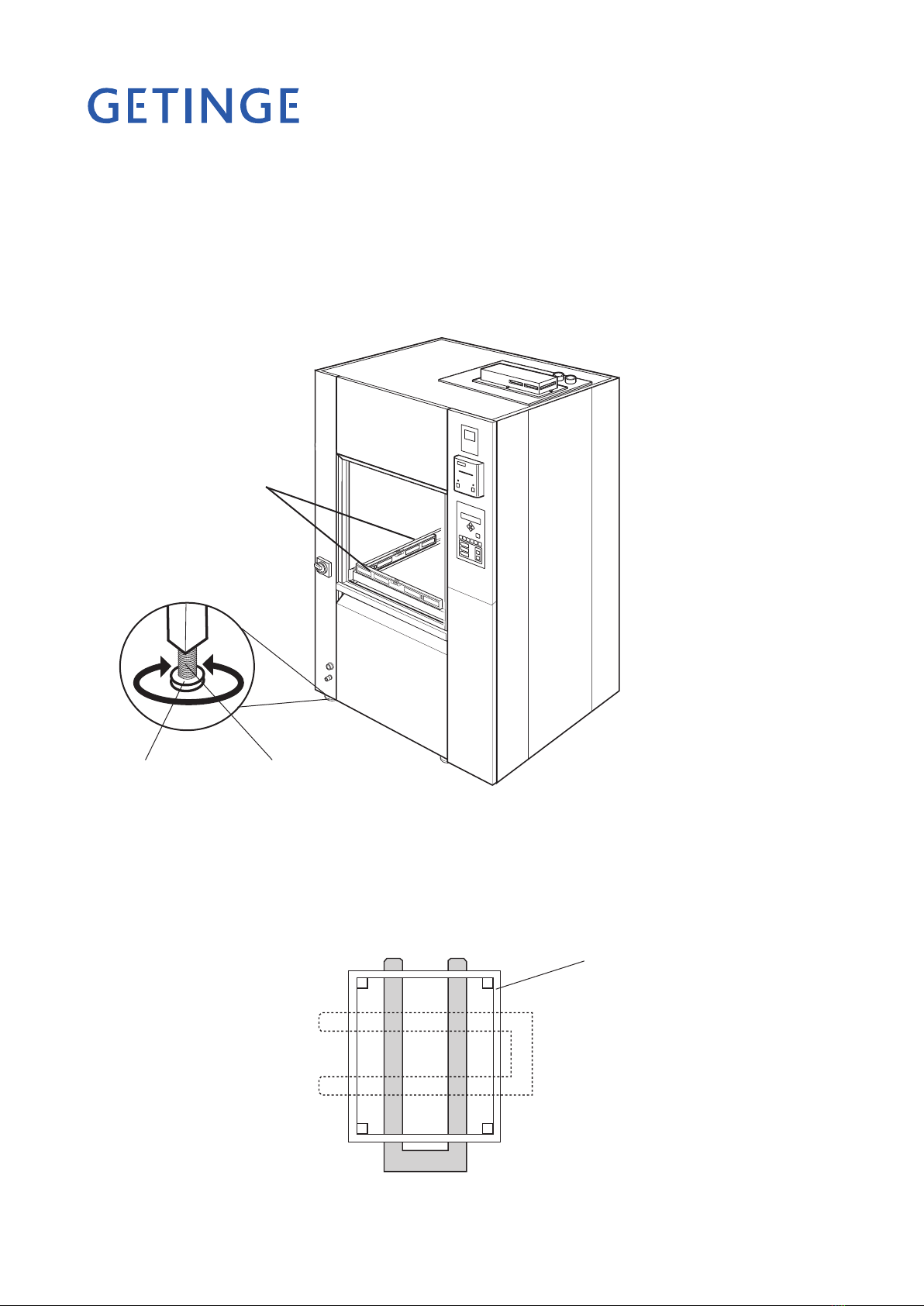
The oor where the machine is to stand must be at and level within ±5 mm.
Pull the machine (on a transport pallet) to the location where it will be installed.
Lift the machine off the pallet.
Position the machine at the chosen location and adjust the feet so that the machine
is stable.
•
•
•
•
Bottom frame
V318
Figure 1. Adjustment
Using a spirit level, check as shown in Figure 1 that the machine is level within ±2 mm.
If you need to move the machine by using a pallet truck:
position the pallet truck forks as shown in Figure 2 so as not to damage the machine.
•
•
V1472
Figure 2. Positioning the pallet truck forks.
Level the
machine with
a spirit level.
Adjusting screwFoot plate
Page 7 of 20
<Doc_INS><Doc_502606400><Rel_A><Lang_GB>
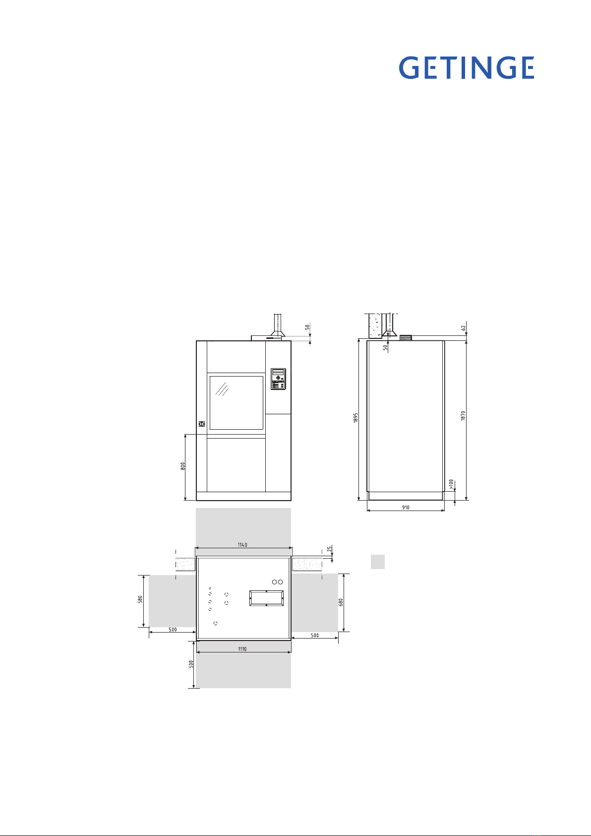
Wall-mounted model
If the machine has double doors and is to be mounted in a wall, the distance be-
tween machine and wall must be 15 mm.
If machines are to be installed next to each other they must be adjusted to the same
height on installation.
Where a plinth plate is used, the height from the oor to the underside of the ma-
chine must be at least 100 mm.
Set the machine horizontal with a spirit level on the side of the machine and adjust
with the feet.
For the loading trolley to work in all the machines, the oor in front of them must
be at and level.
•
•
•
•
•
Figure 3. Installation in a wall
V1475
Service area
<Doc_INS><Doc_502606400><Rel_A><Lang_GB>
Page 8 of 20
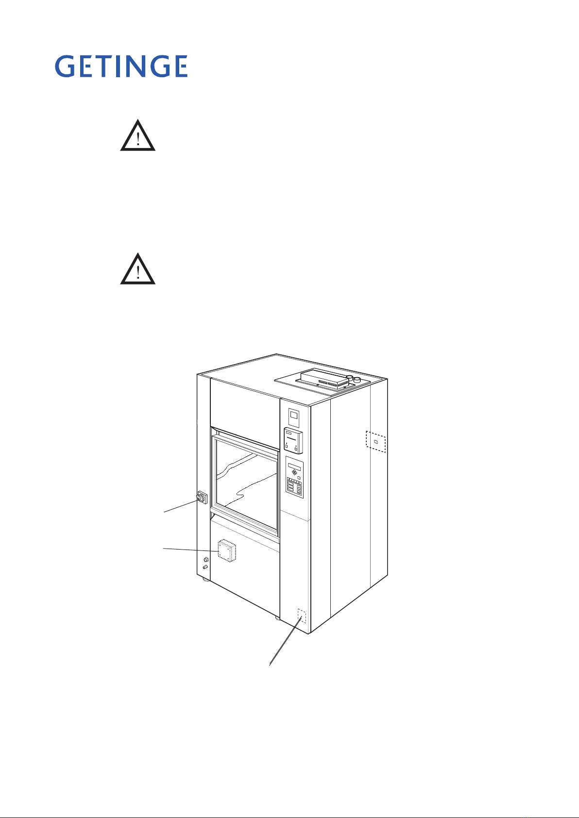
Connecting electric power
Installation may only be done by authorized personnel.
Connect electric power to the machine as follows:
Connect the power supply to the electrical connections of the machine; see the dia-
gram with alternative connection arrangements.
For easier servicing and maintenance, the supply to the machine should be tted
with a lockable isolator with a 3 mm break gap. The isolator must be located in an
easily accessible position on the wall.
It is important that the connection has the correct overcurrent protection. The
correct fuse rating is stated on the type plate.
The main switch on the front of the machine is connected to protective ground (earth)
and to the supply voltage stated on the type plate.
•
•
V1473
Main switch
Figure 4 Electrical connection (see alternative connection arrangements)
Electrical
connection
Type plate
Page 9 of 20
<Doc_INS><Doc_502606400><Rel_A><Lang_GB>
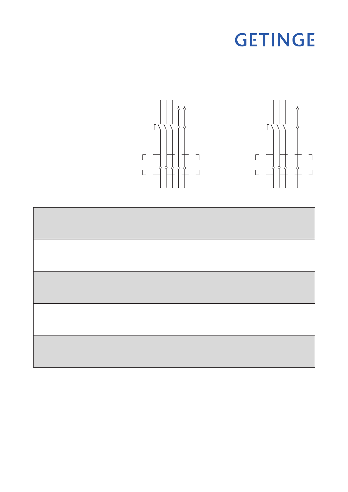
Alternative connection arrangements
Electrically heated 240/415V 3N+PE, 50Hz 21.1kW 31A FUSE 3x32A 240V 3+PE, 60Hz 21.3kW 54A FUSE 3x60A
230/400V 3N+PE, 50/60Hz 19.7kW 30A FUSE 3x32A 230V 3+PE, 50Hz 19.7kW 54A FUSE 3x63A
220/380V 3N+PE, 50/60Hz 17.9kW 29A FUSE 3x32A 208 3+PE, 60Hz 20.5kW 59A FUSE 3x60A
200V 3+PE, 50/60Hz 19.1kW 58A FUSE 3x63A
Steam-heated 240/415V 3N+PE, 50Hz 6.5kW 14A, FUSE 3x20A 240V 3+PE, 60Hz 6.5kW 23A, FUSE 3x25A
230/400V 3N+PE, 50/60Hz 6.5kW 14A, FUSE 3x20A 230V 3+PE, 50Hz 6.5kW 24A, FUSE 3x25A
220/380V 3N+PE, 50/60Hz 6.5kW 14A, FUSE 3x20A 208V 3+PE, 60Hz 6.5kW 26A, FUSE 3x30A
200V 3+PE, 50/60Hz 6.5kW 27A, FUSE 3x32A
Steam-heated 240/415V 3N+PE, 50Hz 11.4kW 18A, FUSE 3x20A 240V 3+PE, 60Hz 11.5kW 30A, FUSE 3x30A
with booster 230/400V 3N+PE, 50/60Hz 10.7kW 17A, FUSE 3x20A 230V 3+PE, 50Hz 10.7kW 29A, FUSE 3x32A
220/380V 3N+PE, 50/60Hz 9.8kW 16A, FUSE 3x20A 208V 3+PE, 60Hz 11.1kW 33A, FUSE 3x35A
200V 3+PE, 50/60Hz 10.4kW 32A, FUSE 3x32A
Steam-heated & 240/415V 3N+PE, 50Hz 11.4kW 18A, FUSE 3x20A 240V 3+PE, 60Hz 11.5kW 30A, FUSE 3x30A
electrically heated 230/400V 3N+PE, 50/60Hz 10.7kW 17A, FUSE 3x20A 230V 3+PE, 50Hz 10.7kW 29A, FUSE 3x32A
220/380V 3N+PE, 50/60Hz 9.8kW 16A, FUSE 3x20A 208V 3+PE, 60Hz 11.1kW 33A, FUSE 3x35A
200V 3+PE, 50/60Hz 10.4kW 32A, FUSE 3x32A
Steam-heated & 240/415V 3N+PE, 50Hz 21.1kW 31A, FUSE 3x32A 240V 3+PE, 60Hz 21.3kW 54A, FUSE 3x60A
electrically heated 230/400V 3N+PE, 50/60Hz 19.7kW 30A, FUSE 3x32A 230V 3+PE, 50Hz 19.7kW 52A, FUSE 3x63A
with booster 220/380V 3N+PE, 50/60Hz 17.9kW 29A, FUSE 3x32A 208V 3+PE, 60Hz 20.5kW 59A, FUSE 3x60A
200V 3+PE, 50/60Hz 19.1kW 58A, FUSE 3x63A
L1 L1 L1-1 L1 T1 L1-2
L2 L2 L2-1 L2 T2 L2-2
N N N-1 N N
L3 L3 L3-1 L3 T3 L3-2
PE PE PE -1 PE PE
-Q01
JB01
MAIN SWITCH
HUVUDBRYTARE
HAUPTSCHALTER
INTERRUPTEUR ELECTRIQUE
ELECTRICAL CONNECTION
EL-ANSLUTNING
ELEKTROANSCHLUSS
CONNEXION ELECTRIQUE
L1 L1 L1-1 L1 T1 L1-2
L2 L2 L2-1 L2 T2 L2-2
L3 L3 L3-1 L3 T3 L3-2
PE PE PE -1 PE PE
-Q01
JB01
MAIN SWITCH
HUVUDBRYTARE
HAUPTSCHALTER
INTERRUPTEUR ELECTRIQUE
ELECTRICAL CONNECTION
EL-ANSLUTNING
ELEKTROANSCHLUSS
CONNEXION ELECTRIQUE
<Doc_INS><Doc_502606400><Rel_A><Lang_GB>
Page 10 of 20
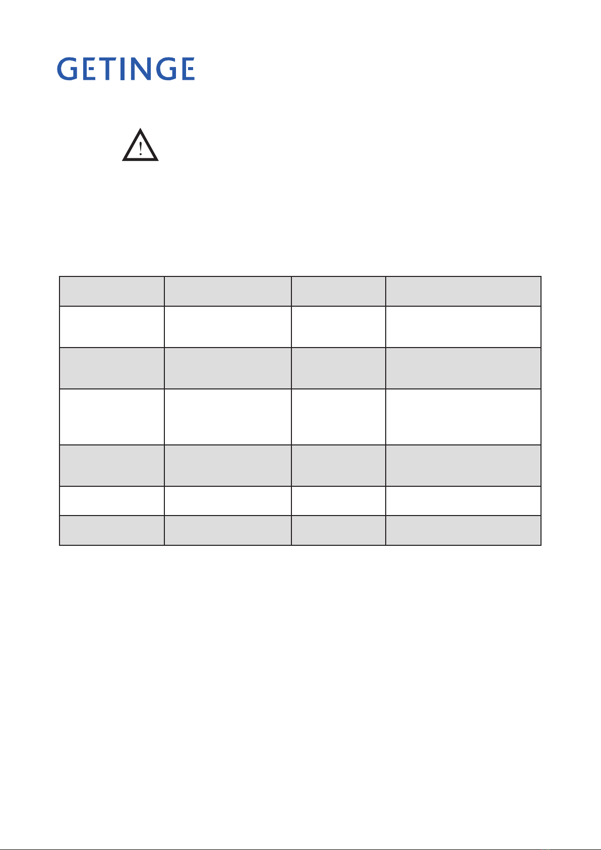
Connecting water, steam, waste and dryer
Installation may only be done by authorized personnel.
Provide water and, if required, steam connections with separate stopcocks. Flush
out the water and steam pipes that are to be connected to the machine, to prevent
clogging of lters and valves.
Connect the disinfector to cold and hot water and to steam and condensate connec-
tions, if used. The connections must meet the following requirements:
•
•
* Where the pressure is lower than 100 kPa a separate feeder pump must be used.
** At chamber depth = 720 mm
*** At chamber depth = 800 mm
Note:
Distilled or de-ionized water must have a conductivity of less than 40 µS/cm.
Connection Pressure Flow rate
Cold water 3/4” (20 mm) male 100-800 kPa approx 33 liters/phase**
approx 40 liters/phase***
Hot water 3/4” (20 mm) male 100-800 kPa approx 33 liters/phase**
approx 40 liters/phase***
Dist. water/
de-ion. water 3/4” (20 mm) male 100-800 kPa* approx 33 liters/phase***
approx 40 liters/phase***
Steam 1/2” (15 mm) female 300-500 kPa 0.9 to 1.0 kg/min
(300 kPa)
Condensate 1/2” (15 mm) female
Compressed air 1/2” (15 mm) female 4 to 8 bar
Altri manuali per 86 SERIES
2
Questo manuale è adatto per i seguenti modelli
1
Indice
Altri manuali Getinge Attrezzature per la pulizia

Getinge
Getinge Decomat 4656 Manuale utente

Getinge
Getinge 88-SERIES Manuale utente

Getinge
Getinge 86 SERIES Manuale utente

Getinge
Getinge S-606 Manuale utente

Getinge
Getinge 46-2 Manuale utente

Getinge
Getinge Decomat 9900 Series Istruzioni operative

Getinge
Getinge FD1800 Manuale utente

Getinge
Getinge Castle 7900 Manuale utente


